


31.
Place (1) .010” magazine shims (#30) under the magazine foot,
between magazine and side plate. Other shims may be added
or subtracted to get the proper drop in the magazine shoe. See
Magazine Adjustment Procedure
.
32.
Insert jaw bolts (#34) through the spring spool bracket,
magazine, shims, side plate, jaw bushing, side plate, latch
spring (#17) and washers (#18). Secure jaw bolts with nylock
nuts (#19). Do not over tighten jaw bolts, jaws must still pivot
freely.
33.
Tighten button head cap screw (#28) at the rear of magazine.
34.
After all adjustments to the tool are made, the trigger guard is
secured with button head screw (#42).
INSTALLATION PROCEDURE / ADJUSTMENTS
Magazine
1.
Before tightening jaw bolts (#34), insert approximately .010”
of shims.
2.
Tighten bolts and check magazine shoe (#29) for proper fit.
3.
When shimmed correctly, and with the feeder blade in the
forward position, the shoe should have approximately
.010”(.25mm) float up and down.
4.
Cycle tool and check for proper ring closure. If feeder blade
hits rear of shoe, add another shim. Shims (#30) are available
in two thickness’ of .005”(.013mm) and .010”(.25mm).
5.
When the tool is completely re-assembled, check to insure that
magazine (#31) is parallel to housing (#47).
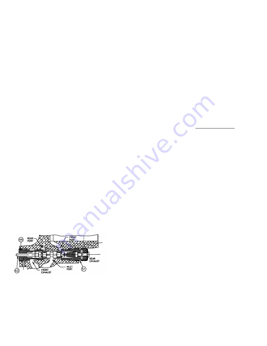
Throttle valve
Follow these steps after completing tool assembly in order to
minimize the time and effort required for optimum throttle valve
adjustment:
1.
Using the valve stem, slowly screw in the front valve seat
(#44) until it bottoms, then back it out 1-1/2 turns.
2.
Do the same with the rear valve seat (#51).
3.
Attach an air line and fully depress the trigger. AIR SHOULD
LEAK OUT THE REAR VALVE SEAT.
While depressing
the trigger,
slowly turn in the rear valve seat (#52) until the air
stops leaking.
4.
Release the trigger. AIR SHOULD LEAK OUT OF THE
HANDLE. Place a 3/16 wrench on the trigger valve stem
(#43) and turn the front valve seat (#44) in slowly until the air
stops leaking from the handle.
5.
Gently depress the trigger. Air should flow evenly from the
rear exhaust to the handle exhaust.
6.
The valve should now be adjusted - test the tool.
7.
Tighten the front and rear valve seat locking set screws (#8)
and re-test the tool.
TOOL LEAKS AIR OR IS SLUGGISH
1.
If tool is leaking air in the throttle area, see “Throttle Valve
Adjustment” section.
2.
Should the tool leak air in both the triggered and rest positions,
a damaged piston o-ring may be the cause. Once the piston o-
ring has been replaced, lubricate with lithium grease.
3.
Put a few drops of light oil into the inlet fitting to lubricate the
piston o-ring if tool is running sluggish.
4.
If the tool is operating too quickly for the operator, remove
button head cap screw (#28) and replace with set screw, jam
nut and shakeproof washer (part numbers SC25, SC15 and
SC28). The set screw can be used as an air flow control
device.
CONVERTING TO A LEFT HANDED TOOL
1.
Remove (2) jaw bolts, nuts, washers and (1) latch spring (#34,
#19, #18, and #17).
2.
Remove (4) button head cap screws (#1).
3.
Remove magazine assembly and pusher system.
4.
Remove latch (#20) and move to other side.
5.
Remove jaws (#21 and #23) and replace them back in the
opposite way.
6.
Place magazine assembly and pusher system onto other side.
7.
Replace latch spring and fasteners.
LUBRICATION
1.
The “SC” series Flex-C tools are designed for long, trouble-
free service with minimal air line lubrication. (If an in-line
lubricator is used, it should be set at the minimum rate of
flow.)
2.
Excess oil in the tool will attract dirt, lint, and the adhesive
material used in collating the fasteners, preventing smooth
operation. When lubrication is used, always use a good
grade
of 5W non-detergent oil with no additives
.
3.
When servicing or repairing tool use
lithium grease
on all
moving parts.
FILTER AND REGULATOR
The air line should always contain a filter and regulator unit to
provide the tool with a constant flow of clean, dry air. If moisture
and contaminates are allowed to enter the tool, the tool’s
serviceable life will be decreased.
TIPS ON EXTENDING TOOL LIFE
The serviceable life of the “SC” series tools can be extended greatly
by using the following guidelines:
1.
Always use Stanley Fastening Systems brand fasteners. Never
replace worn or broken parts with anything other than genuine
Stanley Fastening Systems parts.
Generic fasteners
may
shorten the life of your Flex-C tool and
will void
the
manufacturer’s warranty.
2.
Keep your tool(s) clean and dry. Always use clean, dry air and
never exceed the recommended air pressure.
3.
Use of this tool at minimum air pressure required for the work
at hand will greatly extend the life of the tool.
4.
Exercise caution not to drop equipment. Tools dropping onto
the floor or ground is a primary reason for parts replacement.
HELPFUL HINTS FOR FIELD SERVICE TOOL JAMS
1.
The most common reason for jamming problems in the SC tool
is short cycling. Because of the tool’s valve unit, the trigger
must be pulled completely to the rear to ensure positive
functioning of the valve. If the tool is “short cycled,” the feed
mechanism will return forward prematurely in an attempt to
pick up a second ring. This will most likely cause a jam.
2.
If a jam occurs, pull pusher and rings back on magazine. Point
tool away from yourself and others, and cycle tool slowly.
This should force jammed ring(s) out of jaw mechanism.
3.
If procedure “2” does not clear the tool,
disconnect air
, lay
tool on a clean flat surface and remove top jaw bolt and nut,
and pull top jaw and bushing from tool. Jammed rings are now
exposed and may be removed from tool. Remove build up of
dirt, lint, and any other foreign debris and check for worn or
damaged parts. Re-assemble in reverse order.
4.
Replace worn or damaged parts to keep tool operating
properly.
5
of
6
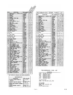
01/03
Содержание SC743
Страница 2: ...2 of 6 01 03...
Страница 3: ...3 of 6 01 03...


