background image

10

ENGLISH

(Original instructions)

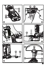
Installing and Removing the Battery Pack from 

the tool

Warning!

 Make certain the lock-off button is engaged to 

prevent switch actuation before removing or installing battery.

To install battery pack (Fig. C)

u

Insert battery pack firmly into tool until an audible click is 

heard as shown in figure C. Ensure battery pack is fully 

seated and fully latched into position.

To remove battery pack (Fig. D)

u

Depress the battery release button (6b) as shown in 

figure D and pull battery pack out of tool.

Storage hook (Optional extra) (Fig. E)

Warning!

 To reduce the risk of serious personal injury, 

place the forward/reverse button in the lock-off position or 

turn tool off and disconnect battery pack before making 

any adjustments or removing/installing attachments or 

accessories. An accidental start-up can cause injury.

Warning!

 To reduce the risk of serious personal injury, ensure 

the screw (10) holding the storage hook is secure.

Note: When attaching or replacing the storage hook (9), 

use only the screw (10) that is provided. Be sure to securely 

tighten the screw.

If the hook is not desired at all, it can be removed from 

the tool.

To move the storage hook, remove the screw (10) that holds 

the storage hook (9) in place.

Note: Various trackwall hooks and storage configurations 

are available.

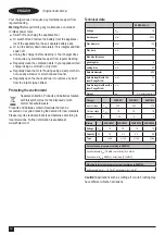
Please visit our website www.stanley.eu/3 for 

further information.

Fitting and removing the guard (Fig. F, G)

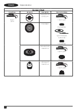
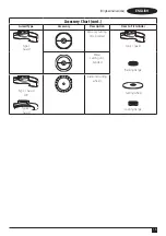
The tool is supplied with a guard intended for grinding 

purposes. Ensure you use the correct guard specific for the 

intended operation. If the unit is intended to perform cutting 

off operations, a guard (16, Fig G) specific for this operation 

must be fitted .

Fitting

u

Place the tool on a table, with the spindle (11) facing up.

u

Release the clamping lock (12) and hold the guard (5) 

over the tool as shown.

u

Align the lugs (13) with the notches (14).

u

Press the guard down and rotate it counterclockwise to 

the required position.

u

Fasten the clamping lock (12) to secure the guard to 

the tool.

u

If required, tighten the screw (15) to increase the 

clamping force.

Removing

u

Release the clamping lock (12).

u

Rotate the guard clockwise to align the lugs (13) with the 

notches (14).

u

Remove the guard from the tool.

Warning! 

Never use the tool without the guard.

Switching on and off

u

To switch on, slide the lock off switch (1) forward then 

press and hold the trigger switch (2).

u

To switch off, release the trigger switch (2).

Warning!

 Do not switch the tool on or off while under load.

Warning!

 Always slide the lock off switch (1) backwards to the 

locked position when the tool is not in use.

Hints for optimum use 

u

Firmly hold the tool with one hand around the side handle 

and the other hand around the main handle.

Surface grinding with grinding wheels

u

Allow the tool to reach full speed before touching the tool 

to the work surface.

u

Apply minimum pressure to the work surface, allowing the 

tool to operate at high speed. Grinding rate is greatest 

when the tool operates at high speed.

u

Maintain a 20˚ to 30˚ angle between the tool and 

work surface.

u

Continuously move the tool in a forward and back motion 

to avoid creating gouges in the work surface.

u

Remove the tool from work surface before turning tool off. 

Allow the tool to stop rotating before laying it down.

Edge grinding with grinding wheels

Wheels used for cutting and edge grinding may break or kick 

back if they bend or twist while the tool is being used to do 

cut-off work or deep grinding. To reduce the risk of serious 

injury, limit the use of these wheels with a standard  

Type 27 guard to shallow cutting and notching (less than  

13 mm in depth). The open side of the guard must be 

positioned away from the operator. For deeper cutting with a 

Type 1 cut-off wheel, use a closed Type 1 guard. 

u

Allow the tool to reach full speed before touching the tool 

to the work surface.

u

Apply minimum pressure to the work surface, allowing the 

tool to operate at high speed. Grinding rate is greatest 

when the tool operates at high speed.

u

Position yourself so that the open-underside of the wheel 

is facing away from you.

u

Once a cut is begun and a notch is established in the 

workpiece, do not change the angle of the cut. Changing 

the angle will cause the wheel to bend and may cause 

wheel breakage. Edge grinding wheels are not designed 

to withstand side pressures caused by bending.

Содержание Fatmax SFMCG400

Страница 1: ...www stanley eu SFMCG400 2 1 4 5 3 7 6 ...

Страница 2: ...2 English original instructions 4 ...

Страница 3: ...3 6 8 8b 8a A 6 6a B 6 C 6 6b 9 10 D E 5 14 13 15 12 14 11 F ...

Страница 4: ...f your body is earthed or grounded c Do not expose power tools to rain or wet conditions Water entering a power tool will increase the risk of electric shock d Do not abuse the cord Never use the cord for carrying pulling or unplugging the power tool Keep cord away from heat oil sharp edges or moving parts Damaged or entangled cords increase the risk of electric shock e When operating a power tool...

Страница 5: ...s injury u Operations such as sanding or polishing are not recommended to be performed with this power tool f Dress properly Do not wear loose clothing or jewellery Keep your hair and clothing away from moving parts Loose clothes jewellery or long hair can be caught in moving parts g If devices are provided for the connection of dust extraction and collection facilities ensure these are connected ...

Страница 6: ...es only when performing an operation where the cutting tool may contact hidden wiring Contact with a live wire will also make exposed metal parts of the power tool live and could give the operator an electric shock u Never lay the power tool down until the accessory has come to a complete stop The spinning accessory may grab the surface and pull the power tool out of your control u Do not run the ...

Страница 7: ... with and behind the rotating wheel When the wheel at the point of operation is moving away from your body the possible kickback may propel the spinning wheel and the power tool directly at you u When wheel is binding or when interrupting a cut for any reason switch off the power tool and hold the power tool motionless until the wheel comes to a complete stop Never attempt to remove the cut off wh...

Страница 8: ...de are shown on the tool Warning To reduce the risk of injury the user must read the instruction manual O Wear safety glasses or goggles when operating this tool f Wear ear protection when operating this tool Additional safety instructions for batteries and chargers Batteries u Never attempt to open for any reason u Do not expose the battery to water u Do not store in locations where the temperatu...

Страница 9: ...harger 8 into an appropriate outlet before inserting battery pack 6 u The green charging light 8a will blink continuously indicating that the charging process has started u The completion of charge will be indicated by the green charging light 8a remaining ON continuously The battery pack 6 is fully charged and may be removed and used at this time or left in the charger 8 u Charge discharged batte...

Страница 10: ...ving u Release the clamping lock 12 u Rotate the guard clockwise to align the lugs 13 with the notches 14 u Remove the guard from the tool Warning Never use the tool without the guard Switching on and off u To switch on slide the lock off switch 1 forward then press and hold the trigger switch 2 u To switch off release the trigger switch 2 Warning Do not switch the tool on or off while under load ...

Страница 11: ...ficulty breathing Note Only those dust masks suitable for working with lead paint dust and fumes should be used Ordinary painting masks do not offer this protection See your local hardware dealer for the proper respiratory protection u NO EATING DRINKING or SMOKING should be done in the work area to prevent ingesting contaminated paint particles Workers should wash and clean up BEFORE eating drink...

Страница 12: ...hold waste Products and batteries contain materials that can be recovered or recycled reducing the demand for raw materials Please recycle electrical products and batteries according to local provisions Further information is available at www 2helpU com Technical data SFMCG400 H1 Voltage VDC 18 Rated speed min 1 9000 Disc diameter mm 125 Disc bore mm 22 Max disc thickness grinding disc mm 6 cuttin...

Страница 13: ...t14 18 2800 Mechelen Belgium 25 10 2019 Guarantee STANLEY FATMAX is confident of the quality of its products and offers consumers a 12 month guarantee from the date of purchase This guarantee is in addition to and in no way prejudices your statutory rights The guarantee is valid within the territories of the Member States of the European Union and the European Free Trade Area To claim on the guara...

Страница 14: ... Description How to Fit Grinder Type 27 Guard Depressed centre grinding disc Type 27 guard Backing flange Type 27 depressed centre wheel Locking flange Wire wheels Wire wheels with threaded nut Type 27 guard Wire wheel Wire cup with threaded nut Type 27 guard Wire brush ...

Страница 15: ...ry Chart cont Guard Type Accessory Description How to Fit Grinder Type 1 Guard Masonry cutting disc bonded Type 1 guard Backing flange Cutting wheel Locking flange Metal cutting disc bonded Type 1 Guard OR Type 27 Guard Diamond cutting wheels ...

Страница 16: ...N717794 REV 01 11 2019 United Kingdom STANLEY FATMAX Tel 01753 511234 270 Bath Road Fax 01753 572112 Slough Berkshire SL1 4DX www stanleytools co uk ...

Отзывы: