background image

EX5500 Controller Installation & Configuration Guide 


23 


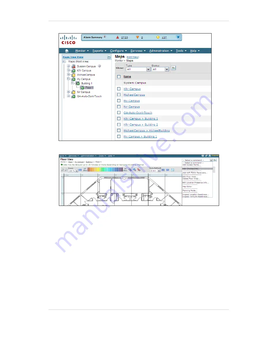
6.


Select A

dd Chokepoint

 and click 

Go


7.


Check the relevant Exciter and click 

OK

. You are returned to the relevant floor 

area.  

8.


Locate the added Exciter on the map and click 

Save

9.


Select 

Services, Synchronize Services 

and synchronize the relevant MSE. 

10.


Open System Manager and configure the Exciter. 

Содержание EX5500

Страница 1: ...EX5500 Controller Installation Configuration Guide 0981 029 Rev A ...

Страница 2: ...are Trademark Acknowledgements AeroScout is a trademark of Stanley Black Decker Other brand products and service names are trademarks or registered trademarks of their respective holders Below is a partial listing of other trademarks or registered trademarks referenced herein Cisco is a trademark of Cisco Systems Inc Sun Sun Microsystems the Sun Logo Java JRE and all other Sun trademarks logos pro...

Страница 3: ...Power Connections to EX5500 10 Chaining the EX5500 Controllers 13 Resetting the EX5500 Controller IP Address 15 Configuring the EX5500 Controller 16 Configuring the Controller via Cisco MSE 22 Mounting the Controller and External LF Antenna 24 Mounting the Controller or External LF using the Exciter Mounting Clip 25 EX5500 and Accessories Model Numbers 27 EX5500 Specifications 28 ...

Страница 4: ...l capabilities The EX5500 Controller triggers Hugs Tags as they pass through an Egress or as they approach the Controller Tags in turn transmit a message to either the Location Receivers or to compatible Access Points within range The Controller can activate or deactivate Tags program them or even instruct Tags to operate in a specific way for example to blink This provides instant acknowledgment ...

Страница 5: ...barcode scanning Real Time Alerts Organizations can use Stanley Healthcare Controllers to trigger automated events and alerts based on the current location of an asset For example in a shipping yard notifications can be sent when vehicles pass through gates and enter or exit a certain dock or bonded area Security applications Stanley Healthcare Controllers can be installed at the entrances of rest...

Страница 6: ...tion when planning and designing the deployment Figure 2 EX5500 Positioned at a Doorway Triggering a Tag Tag behavior modification The EX5500 Controller can wirelessly activate and deactivate Tags Tag battery life can be extended by switching them off when they leave a defined tracking area through a gate or doorway The Controller can also be configured to change the Tag transmission rate temporar...

Страница 7: ...g the need for a physical network connection In the offline mode however remote configuration and monitoring is not available EX5500 LED Status Indicators The EX5500 has a single LED that changes color based on the Controller status as follows Constant Green The Controller is on and working correctly Blinking Green The Controller is offline Constant Orange The Controller is being bypassed for exam...

Страница 8: ...iguration Guide 8 EX5500 Controller Connector Panel The EX5500 Controller has five connectors and two relay switches on the connector panel Figure 4 Stanley Healthcare EX5500 Connector Wiring Figure 5 Stanley Healthcare EX5500 Connectors ...

Страница 9: ...tion to change IP for example For this option you need a special 10 pin RJ45 to DB9 serial cable AeroScout PN 40031500000 4 Chain OUT and Control Connector RJ 45 connector This connector is used for distributing power and data to chained Exciters and to connect the External LF Antenna device The output voltage is 12 V DC 0 5A maximum 5 Termination Switch For defining the termination settings in a ...

Страница 10: ...e following is a brief summary of available powering and networking options Usage Option Description Single EX5500 not connected to a network EX5500s can be used as standalone devices that function independently without any network connection In this case you only need to connect the EX5500 to the power supply Using System Manager set the device as not connected to the network Single EX5500 connec...

Страница 11: ...plies both the power and the network connection Note PoE standard 802 3af class 0 allows power for a single EX5500 Controller When using PoE with the other chained Exciters a PoE connection must be made to every second Exciter in the chain In addition the LAN connectivity that the PoE supplies is not used for slave Exciters in a chain Slave Exciters receive data from the Master Exciter via the Cha...

Страница 12: ...k must be connected separately to the EX5500 Controller s LAN connector This adaptor is most commonly used for chained Exciters It can power up to two Exciters Power Connection Summary The following table summarizes the power connection options Power Supply Input Output Max Current Available Power Maximum of Exciters with One Source PoE single port injector 100 240 VAC 50 60 Hz 48 VDC 0 32 A 1 15 ...

Страница 13: ...5500 Controllers The system treats chained Exciters as a single device with a single ID Transmissions do not interfere with one another Each Exciter must be positioned to allow transmission range overlap between neighboring Exciters This ensures full coverage of the area Figure 7 shows 5 chained Exciters their connections and the state of each Exciter termination switch Figure 8 EX5500 Chaining Us...

Страница 14: ...rs are then connected as follows Slave OUT to Slave IN 4 The Termination Switch of the Master Exciter and the last Slave Exciter in the chain must be set to On o o On the other Slave Exciters it must be set to Off o o 5 The Master Slave configuration is set via System Manager Slave Exciters inherit the Master Exciter ID and LF configuration as well as the transmission range ...

Страница 15: ...cient and some overlap exists between the chained Exciters LF coverage Connected to network Make sure the Connected to network checkbox is unchecked Chaining and External Connections Check the Exciter is Slave Checkbox Resetting the EX5500 Controller IP Address You can reset the EX5500 Controller s IP address to the factory default value The default IP address is 192 168 1 178 Press the IP Reset b...

Страница 16: ...tings in the System Parameters and the Exciter Properties dialog boxes to be configured System Manager can automatically detect the Exciter Model Once detected a number of settings are automatically configured by System Manager System Parameters 1 Select Configuration System parameters The System Parameter dialog box opens 2 Select the Devices tab a Set the Wi Fi Receiver Multicast Address Filter ...

Страница 17: ...e Exciter Properties dialog box opens 3 In the Exciter Properties dialog box General Module select the Settings tab a Enable the Internal LF Exciter b Select and Enable the Wi Fi Receiver Selecting and Enabling the Wi Fi Receiver Module adds the Controller module in the Exciter Modules pane c Select the General Transmission Parameters tab d Set the LF Transmission Interval to 200 milliseconds ...

Страница 18: ...LF Exciter Module a Select the Tag Reactions tab b Ensure the Send leaving Exciters range notification option is unavailable c Select the Tag Transmission Parameters tab d Tag Repetitions of an Exciter select the Number of Repetitions option e Set the Number of Repetitions to 3 ...

Страница 19: ...EX5500 Controller Installation Configuration Guide 19 f Select the Advanced Tab g Ensure the Make Tag Blink option is set to Exclude 5 Select the Controller Module Configure as follows ...

Страница 20: ...igger device box c Check the box Connected to door Sensor as required The Exciter sends SNMP traps to MobileView when the door is open and closed Failsafe Mechanism a Select the Enable failsafe option to allow the Exciter to monitor the network status b Enter a time lapse period in seconds in the Failsafe Timeout field If a network connection is not registered within this period the failsafe mecha...

Страница 21: ...oot are compatible with the current version of Stanley Healthcare Engine and the Exciter hardware version Consult Stanley Healthcare Support for appropriate firmware versions 10 Position and mount each EX5500 Controller in the site according to the site survey recommendations 11 Align the EX5500 Controller position according to the required coverage area 12 If you wish to define an EX5500 Controll...

Страница 22: ...uring the Controller via Cisco MSE Follow this procedure 1 Open the WCS and select Configure Chokepoints 2 Select Add Chokepoint 3 Enter the MAC address Name and Static IP Address 4 Click Save 5 Select Monitor Maps and then the relevant campus building and floor ...

Страница 23: ...int and click Go 7 Check the relevant Exciter and click OK You are returned to the relevant floor area 8 Locate the added Exciter on the map and click Save 9 Select Services Synchronize Services and synchronize the relevant MSE 10 Open System Manager and configure the Exciter ...

Страница 24: ...g of the device Figure 9 Controller mounted on a Floating Ceilings Mounting the Controller on a Wall Mount the Exciter with the Stanley Healthcare logo facing up Attach the Controller to the wall using the two screw mounts on the bottom casing Fixing the External LF Antenna to a Floating Ceiling Attach the antenna to the false ceiling using the ceiling mounts located on the bottom casing Figure 10...

Страница 25: ...oyments where mounting on the ceiling grid is not possible Figure 11 Exciter Mounting Clip SKU EXAC 140 1 Position the Mounting Clip on a standard 60cm 24 grid false ceiling a Snap the Mounting Clip onto the topside of the T Grid using the snaps on the ends of the clip Figure 12 Exciter Mounting Clip positioned on a grid of a false cieling 2 Prepare the Ceiling Tile a Measure and mark the required...

Страница 26: ...26 b Screw them into the Mounting clip The screw heads should remain 2 3cm below the ceiling tile c Attach the Controller or LF Antenna using the two screw mounts on the bottom casing Figure 13 External LF Antenna mounted using the Exciter Mounting Clip ...

Страница 27: ...ector Tool EXD 1000 Tool for visualizing the effective LF Exciter transmission field Analyzes the Exciter coverage during deployment Includes a PC application and detector hardware that can be connected via USB to a PC External LF Antenna ANT 4200 External LF Antenna Device Powered directly from the Exciter Includes mounting plate and a ceiling mount Exciter Mounting Clip EXAC 140 Heavy duty Mount...

Страница 28: ... 20 in up to 6 5m 21 3ft in intervals of 0 5m 20 in LF Channel 125kHz Field intensity limits 37 3dBµA m at 10m ETSI Propagation limits 21 8dBµV m at 300m FCC Modulation ASK Network Interface Ethernet RJ 45 Power Input voltage 12 24 48VDC PoE 802 3af 48VDC Maximum power consumption 10W Maximum power consumption of External LF Antenna 5W Environmental Operating temperature 0 to 50 C 32 F to 122 F Hu...

Страница 29: ...a Increase the distance between the device and the receiver Connect the device to an outlet on a circuit different from the one that supplies power to the receiver Consult the dealer or an experienced radio TV technician WARNING Changes or modifications to this unit not expressly approved by the party responsible for compliance could void the user s authority to operate the equipment This device c...

Страница 30: ...by consulting training and Transformational Lean process reengineering Stanley Healthcare is proud to be part of Stanley Black Decker Inc For more information visit www StanleyHealthcare com Stanley Healthcare 1300 Island Drive Suite 202 Redwood City CA 94065 Tel 1 650 596 2994 Fax 1 650 596 2969 E mail info aeroscout com Europe Middle East Africa Office Tel 32 2 709 29 49 Fax 32 15 30 80 99 E mai...

Отзывы: