background image

page 5 of 12 
 

5.


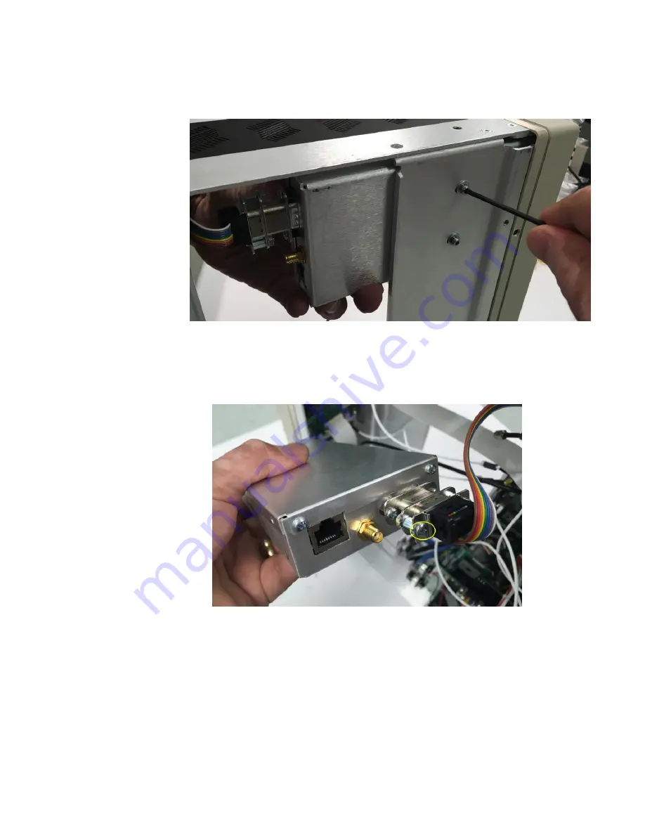
While supporting the metal preamplifier enclosure, remove the two #6 size hex 
screws securing the preamp to the chassis, using a 7/64  hex driver. Be careful to 
not lose the washers beneath each hex screw: 


6.


Carefully back the preamp enclosure out of the instrument chassis.  
6.1.


Pull the box back from the front panel so the BNC connectors all slide back 
out of the instrument. Be careful to not tug on the remaining ribbon cable 
connected to the preamp.   

6.2.


With the preamp enclosure removed from the chassis, remove the two 
screws holding the ribbon cable to the preamp: 


Once the screws are removed, disconnect the ribbon cable from the preamp.  


Содержание SR86 Series

Страница 1: ...hich the user suspects a damaged or destroyed input JFET Symptoms of a damaged JFET can be excess noise or partial or complete signal loss The SR86x series lock in amplifiers are designed to permit th...

Страница 2: ...strument 1 Turn off power to the unit and remove the AC power cord Disconnect all other cables from the SR865 To access the preamplifier the top and bottom covers must be removed from the unit 2 Remov...

Страница 3: ...2 3 Remove the top cover Turn the instrument upside down carefully resting on the top Remove the 4 large black screws from the bottom cover 2 on each side 2 4 Remove the 6 small black screws from the...

Страница 4: ...urn the instrument on its side so the SIGNAL section is near the top 4 Disconnect the white coax cable and the RJ style modular cable from the preamplifier enclosure Do not attempt to disconnect the r...

Страница 5: ...ly back the preamp enclosure out of the instrument chassis 6 1 Pull the box back from the front panel so the BNC connectors all slide back out of the instrument Be careful to not tug on the remaining...

Страница 6: ...7 Open the preamp assembly by removing the two small hex screws from the front using the 0 050 hex driver and the 6 Phillips head screws Remove the lid to the preamp assembly 8 Locate Q202 the input J...

Страница 7: ...cement JFET to match the removed part Notice that two of the socket positions on Q202 are left empty it is critical that the new part be installed with this same orientation leaving the top and bottom...

Страница 8: ...hould be exterior to the walls 11 2 Loosely thread the two small hex screws in the front but do not tighten 11 3 Loosely thread the remaining 6 Phillips screws again without tightening 11 4 Tighten th...

Страница 9: ...13 1 Check that the BNC connectors are fully engaged and flush to the front panel partial fully 13 2 Apply pressure to keep the preamp engaged when reinstalling the two 6 hex screws Be sure to instal...

Страница 10: ...screws 16 2 Loosely thread the 4 large black screws 16 3 Tighten the 6 small black screws 16 4 Tighten the 4 large black screws 17 Install a 50 terminator or a shorting cap onto the A input BNC 18 Re...

Страница 11: ...Offset Cal tile to calibrate the 100 mV DC range 24 4 Press the INPUT RANGE Down Arrow button to select 30 mV input range Touch the Offset Cal tile to calibrate the 30 mV DC range 24 5 Press the INPU...

Страница 12: ...calibrated power cycle the instrument When the lock in turns on with the 50 or shorting cap still installed and the frequency at 3 0 Hz set by the Offset Cal function verify the displayed R value is...

Отзывы: