background image

(13)

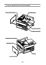
Gate Solenoid

Upper 

Sensor Receiver

Sensor Projector 

Lower

Sheet Presence mSW

Sheet Feed Solenoid

Drive Motor

Relay

Motor Capacitor

Terminal Board

AC Input

Power Supply

Power Switch

Fuse Holder

4A

Control P.C.B. QPW 444

Feed Tray Position mSW

Indication P.C.B. QPW 449

Sheet Delivery Cover mSW

Gate Solenoid

1-480319-0

1-480318-0

COM

NO

NO

COM

AR6622

NSKG115

ML-1765-4P

LCA30S-24

JW-L21RKK

F-65AB

CON2

CON5

CON3

CON4

CON1

COM

NO

1-480319-0

1-480318-0

Y

G

D

1-480319-0

1-480318-0

CON1

CON2

COM

NC

Jumper Pin

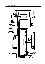
8. Line Diagram

Содержание PF-P310

Страница 1: ...SERVICE MANUAL Standard Horizon PF P310 Paper Folder Read this manual and thoroughly familiarize yourself with its contents before operating or servicing this equipment PF P310 SM ...

Страница 2: ......

Страница 3: ...tions in this manual If you have questions regarding maintenance or this publication please contact our service division This manual is designed to help you to keep the machine in a good operating condition Read study and keep this manual in a safe and convenient place The machine design and specifications are subject to change without notice ...

Страница 4: ...INC cannot anticipate every possible situa tion that might involve a potential hazard The instruction in this manual are therefore not all inclusive 3 Be sure to unplug the power cord when replacing the parts or repairing the machine 4 Take care with the rotating parts when the machine is operated with the covers being opened 5 Use the original HORIZON spare parts when replacing the parts ...

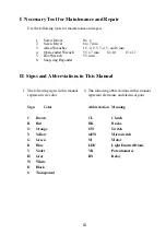
Страница 5: ...h 5 5 mm 6 Snap ring Expander II Signs and Abbreviations in This Manual 1 The following signs in this manual represent wire color Sign Color C Brown R Red O Orange Y Yellow G Green B Blue V Violet H Gray W White D Black S Transparent 2 The following abbreviations in this manual represent electronic and electrical parts Abbreviation Meaning CL Clutch BK Brake SW Switch mSW Microswitch M Motor LED L...

Страница 6: ...air III II Signs and Abbreviations in This Manual III 1 Specifications 1 2 Operation Overview 2 3 Sheet Flow 3 4 How to Remove Cover 4 5 Troubleshooting 5 6 How to Replace Count Sensor 11 7 Sensors and Electronic Parts Descriptions 12 8 Line Diagram 13 9 How to Replace Control Board 14 ...

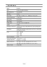
Страница 7: ... Counter 4 digits Fold Measure Indication Buckle stopper position lamp illuminates by pressing fold pattern select button Fold Pattern Single Fold Short Fold Parallel Fold Letter Fold Accordion Fold Gate Fold Cross Fold Power 100 V 50 60 Hz 115 V 60 Hz 230 V 50 Hz Power Consumption 65 W Temperature Humidity Temperature 5 45 Humidity 15 80 RH Machine Dimension Tray Open 771 x 485 x 316 mm 28 x 19 1...

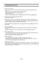
Страница 8: ...ating with stop per handle 5 Press test feed button Clutch will be activated and feed roller will make 1 turn and a sheet is fed Display will indicate 1 If sheet is not piled on feed tray feed roller will not turn and display will remain 0 6 Press start stop button Clutch will be activated and a sheet will be fed and then sheets will be transported continu ously with some intervals only accordion ...

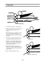
Страница 9: ...stopper in 1st buckle sheet is buckled and the buckled part of sheet is nipped between 2nd drive roller and fold roller 4 1 In the case of single fold deflector moves to the right and sheet is delivered to tray 4 2 In the case of the other folding patterns deflector moves to the left and sheet folded between 2nd drive roller and fold roller is transported to 2nd buckle 5 When sheet reaches to stop...

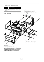
Страница 10: ... 0 10 15 20 25 30 5 二つ 折 片袖 折 内三 つ折 観音 折 四つ 折 紙の セッ ト 印 刷面 はウ ラ向 きで す 外三 つ折 スト ッパ の移 動方 向 L S 1 スト ッパ 2 スト ッパ 10 10 15 15 20 20 25 25 30 30 5 10 10 15 15 20 20 5 PF P310 PEPERFOLDER Front Cover Bind Screw M4 x 8 2 pcs Front cover is installed with the top edge fitted with operation panel Remove front cover by pulling front cover diagonally downward Side Cover Bind Screw M4 x 8 4 pcs 4 How to Remov...

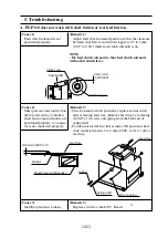
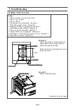
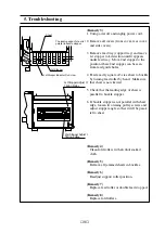
Страница 11: ... does not work with start button or test feed button Remedy 1 Adjust feed clutch solenoid position so that the clearance between clutch lever and clutch stopper is 0 5 to 1 mm 0 02 to 0 04 while feed clutch solenoid is on NOTE Fix feed clutch solenoid so that feed clutch solenoid will not hit clutch lever Remedy 2 Check on microswitch position or replace microswitch after removing feed tray Remove...

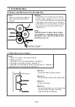
Страница 12: ...ition Remedy 2 Clean fold rollers with alcohol soaked cloth Remedy 3 Replace fold rollers Remedy 4 Check that bush plates are not deformed and that they operate smoothly After that lubricate fulcrum of bush plate Cause Deflector is deformed or deflector drive solenoid is not positioned properly Remedy Adjust deflector so that the clearance between 2nd drive roller and deflector is 0 9 to 1 3 mm 0 ...

Страница 13: ...t of specification 2 Feed rollers are worn out Remedy 1 3 Feed rollers get worse Remedy 1 4 Feed tray does not operate correctly be cause spring is loosen Remedy 2 5 Sheet is caught between feed guides too tight Remedy 3 6 Feed tray pressure is weak Remedy 2 Remedy 1 Replace feed rollers Remedy 2 Check on feed tray movement or replace spring in feeding section Remedy 3 Adjust feed guides Remedy 1 ...

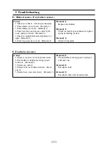
Страница 14: ...ld roller spring is loosen Remedy 2 6 Stopper in buckle is set improperly Remedy 3 7 Fold rollers are dirty with ink Remedy 4 8 Sheets are jammed in buckle Remedy 5 9 Support rollers are set improperly Remedy 6 10 Feed roller or double feed stope pad is worn out Remedy 7 11 Fold roller is worn out Remedy 8 Remedy 1 Adjust feed guides so that feed guides are right angled with front guide and feed g...

Страница 15: ...ray Move 2nd stopper to the position where 2nd stopper can be seen from feed guide holes 4 Feed exactly square A3 size sheet to buckle by turning feed roller by hand Make sure that sheet is not skewed 5 Check that the leading edge of sheet is parallel to buckle stopper 6 If buckle stopper is not parallel with sheet edge loosen two timing pulley screws and adjust stopper angle so that it will be pa...

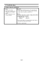
Страница 16: ... Remedy 1 Clean sensor Refer to page 11 If counter does not works correctly in spite of cleaning check on wiring replace sensor or replace control P C B NOTE To check count sensor measure voltage between Pin 3 and Pin 4 in CON 4 on P C B Sheet Presence 3 to 5 V No Sheet 0 to 0 5 V 2 Select short fold or accordion fold with select button to provide interval between each sheet 3 Remove jammed sheets...

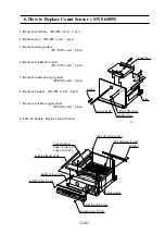
Страница 17: ...nt Sensor Upper Projector Lower Receiver Indication Sign Panel Spring Shaft Spring M5 10W screw Stay Feed Tray B4 8W screw 6 How to Replace Count Sensor S N 061899 1 Remove feed base B4 8W screw 4 pcs 2 Remove stay B4 8W screw 4 pcs 3 Remove slide guided B3 16W screw 6 pcs 4 Remove buckle fix screws B4 12W screw 6 pcs 5 Remove indication sign panel B4 8W screw 4 pcs 6 Remove bracket B4 8W screw 6 ...

Страница 18: ...ト スタート ストップ 折形 紙サ イズ B5 B4 A4 A3 クリ ア スト ッパ の移 動方 向 スト ッパ の移 動方 向 L S S L 2 2 スト ッパ スト ッパ 1 1 スト ッパ スト ッパ スト ッパ の移 動方 向 スト ッパ の移 動方 向 L S 1 1 スト ッパ スト ッパ 2 2 スト ッパ スト ッパ 10 10 15 15 20 20 25 25 30 30 5 10 10 15 15 20 20 5 PF P310 PF P310 PEPERFOLDER PEPERFOLDER 排紙 状態 で 排紙 状態 で 表わ して 表わ して あり ます あり ます 部 長 い 部 長 い 部 短 い 部 短 い 排紙 状態 で 排紙 状態 で 表わ して 表わ して あり ます あり ます 部 長 い 部 長 い 部 短 い 部 短 い 2 2 スト ッパ ...

Страница 19: ...ower Supply Power Switch Fuse Holder 4A Control P C B QPW 444 Feed Tray Position mSW Indication P C B QPW 449 Sheet Delivery Cover mSW Gate Solenoid 1 480319 0 1 480318 0 COM NO NO COM AR6622 NSKG115 ML 1765 4P LCA30S 24 JW L21RKK F 65AB CON2 CON5 CON3 CON4 CON1 COM NO 1 480319 0 1 480318 0 Y G D 1 480319 0 1 480318 0 CON1 CON2 COM NC Jumper Pin 8 Line Diagram ...

Страница 20: ...not be used The count sensor does not operate QPW 444H or after Machine before S N 061899 Use the machine without the jumper pin on QPW 444H Machine after S N 062001 Use the machine with the jumper pin on QPW 444H when the control board is shipped from manufacturer the jumper pin is attached to the board CON2 CON5 CON3 CON4 CON1 Jumper Pin ...

Страница 21: ......

Страница 22: ...Standard Business Systems 10 Connector Road Andover MA 01810 978 470 1920 978 470 2771 PF P310 SM Revised 11 2002 ...

Отзывы: