Page 15
GX1700
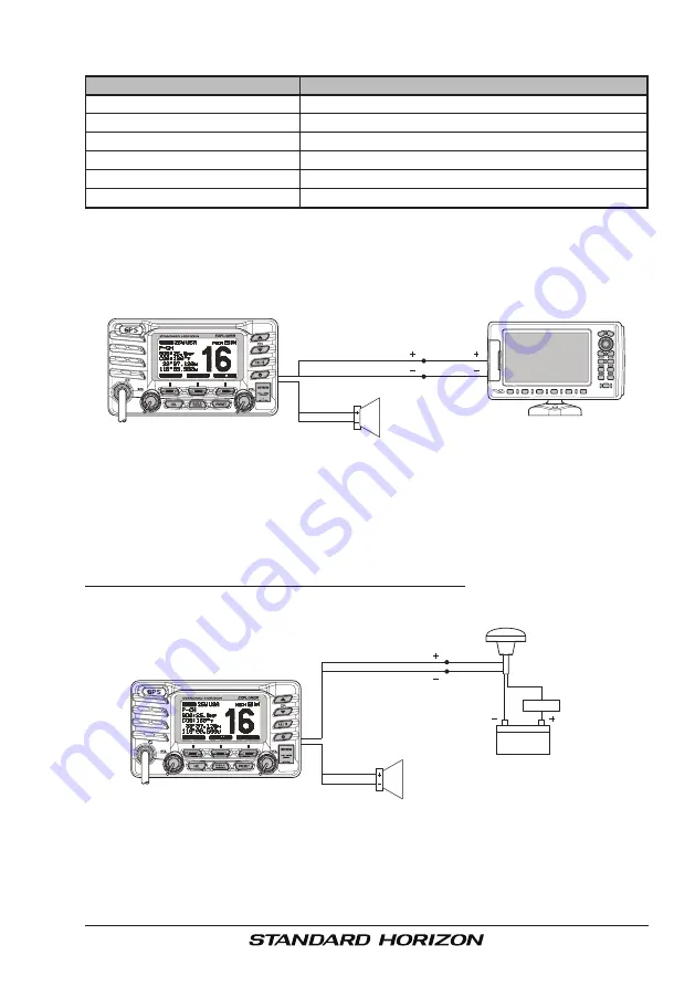
6.5 ACCESSORY CABLE
Wire Color/Description
Connection Examples
WHITE - External Speaker (+)
Connect to external 4 Ohm audio speaker
SHIELD - External Speaker (–)
Connect to external 4 Ohm audio speaker
BLUE - NMEA GPS Input (+)
Connect to NMEA (+) output of GPS
GREEN - NMEA GPS Input (–)
Connect to NMEA (–) output or common ground of GPS
GRAY - NMEA DSC Output (+)
Connect to NMEA (+) intput of GPS
BROWN - NMEA GPS Output (–)
Connect to NMEA (–) input or common ground of GPS
Chart Plotter
External Speaker
Shield
White
Plotter
Connection
Radio Wires
Gray: NMEA DSC Output ( )
GPS Input ( )
GPS Input ( )
Brown: NMEA DSC Output ( )
External Speaker
Shield
White
Radio Wires
Par
Q7000619A
t #:
Standard Horizon
GPS Antenna
Blue: NMEA GPS Input ( )
Black
Black
Red
Brown
Green: NMEA GPS Input ( )
12 V Battery
2 A Fuse
( )
( )
Note
: The GPS antenna is supplied with 30ft of cable
and a connector. To connect the GPS antenna to the
radio, cut off the 5 pin antenna connector, strip the white
insulation to expose the Red, Black and Brown wires and
connect as shown in the diagram. All other wires are not
used and may be cut off. The 2 amp fuse is not included.
: Some GPS Chart plotters have a single wire for NMEA Signal Ground, if this is the case
connect the NMEA Input (–) and NMEA output (–) to the GPS Chart Plotters single NMEA
Signal Ground wire.
6.5.1 Internal GPS
(
DSC Output to a Chart Plotter
)
6.5.2 External GPS or Chart Plotter
(
for GPS
)
The connections below are used when the internal GPS cannot receive a
Fix. The
GX1700
Internal GPS must be turned off (refer to section “
14.9
UNIT POWER
”) and the GPS Selection must be selected to External GPS
(refer to section “
14.9 GPS SELECTION
”).
6.5.2.1 GPS Input - Standard Horizon GPS Antenna

