background image

-9-

BASIC TOOL OPERATION

MAINTAINING THE PNEUMATIC TOOL

When working on air tools, note the warnings in this manual and use extra care 
evaluating problem tools.

CAUTION: Pusher spring (constant force spring).  Caution must be used when working with the spring 

assembly.  The spring is wrapped around, but not attached to, a roller.  If the spring is extended 
beyond its length, the end will come off the roller and the spring will roll up with a snap, with a 
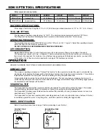
chance of pinching your hand. Also the edges of the spring are very thin and could cut.  Care 
must also be taken to insure no permanent kinks are put in the spring as this will reduce the 
springs force.

REPLACEMENT PARTS:

STAN-TECH replacement parts are recommended.  Do not use modified parts or parts which will not 
give equivalent performance to the original equipment.

ASSEMBLY PROCEDURE FOR SEALS:

When repairing a tool, make sure the internal parts are clean and lubricated.  Use Parker “O”-LUBE or 
equivalent on all “O”-rings.  Coat each “O”-ring with “O”-LUBE before assembling.  Use a small amount of oil
on all moving surfaces and pivots.  After reassembly add a few drops of STAN-TECH Air Tool Lubricant 
through the air line fitting before testing.

AIR SUPPLY-PRESSURE AND VOLUME:

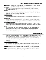
Air volume is as important as air pressure.  The air volume supplied to the tool may be inadequate because of 
undersize fittings and hoses, or from the effects of dirt and water in the system.  Restricted air flow will prevent 
the tool from receiving an adequate volume of air, even though the pressure reading is high.  The results will be
slow operation, misfeeds or reduced driving power.  Before evaluating tool problems for these symptoms, trace 
the air supply from the tool to the supply source for restrictive connectors, swivel fittings, low points containing 
water and anything else that would prevent full volume flow of air to the tool.

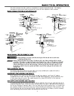
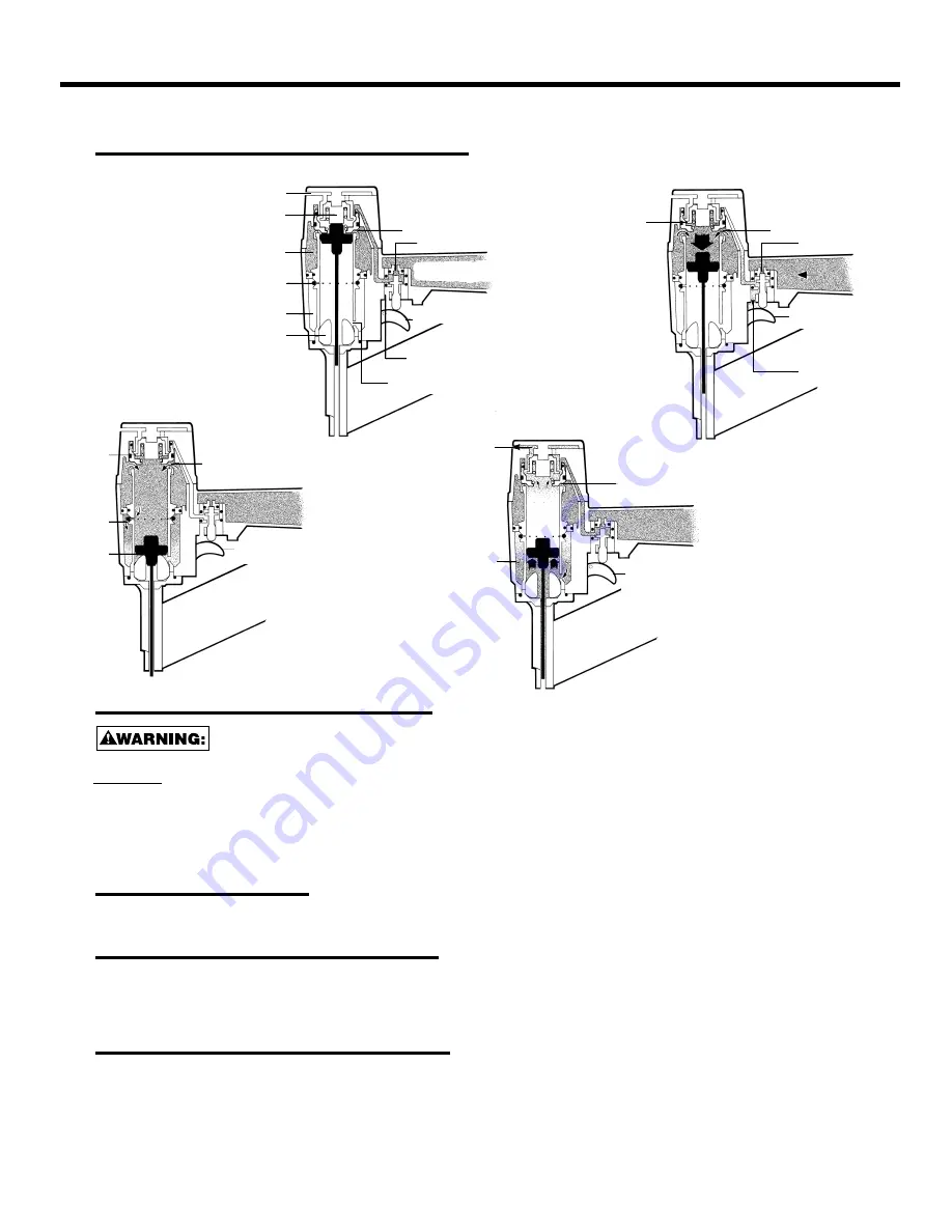
Stan-Tech pneumatic tools are cycled by a compressed air operated single piston design.  The following 
illustrations show the four functional cycles that occur when the tool is operated to drive a fastener:

BASIC SINGLE PISTON STAPLER/NAILER

FIG.1
AT REST

FIG.2
DRIVING STROKE

FIG.3
END OF STROKE
TRIGGER STILL
PULLED

FIG.4
RETURNING

HEAD VALVE CLOSED

EXHAUST

OPEN

AIR IN

RETURN

CHAMBER

PUSHES

PISTON

UPWARD

EXHAUST

STILL

CLOSED

HEAD VALVE OPEN

TRIGGER VALVE
STILL ACTUATED

AIR FLOWS

INTO

RETURN

CHAMBER

PISTON IS

SEALED

AGAINST

BUMPER

TRIGGER VALVE
RELEASED –
AIR PRESSURE RETURNS
TO TOP OF HEAD VALVE

EXHAUST

SEALED BY

PISTON STOP

HEAD VALVE OPEN

TRIGGER VALVE PORT
BLOCKED

AIR RELEASED
FROM ABOVE
HEAD VALVE

TRIGGER VALVE
ACTUATED

EXHAUST

OPEN

HEAD VALVE CLOSED

SLOTS FOR AIR FLOW 
FOR PISTON RETURN

TRIGGER VALVE RELEASED

PASSAGE FOR 
AIR RELEASED FROM HEAD VALVE

TRIGGER VALVE PORT

(TO SUPPLY AIR TO TOP OF HEAD VALVE)

PISTON

STOP

RETURN

CHAMBER

BUMPER

RESERVOIR

OF HIGH

PRESSURE

AIR

HOLES IN

CYLINDER

WALL

RESERVOIR OF 
HIGH PRESSURE AIR

Содержание SDN11PTB

Страница 1: ...E MANUAL BEFORE OPERATING THIS TOOL ALL OPERATORS SHOULD STUDY THIS MANUAL TO UNDERSTAND AND FOLLOW THE SAFETY WARNINGS AND INSTRUCTIONS KEEP THESE INSTRUCTIONS WITH THE TOOL FOR FUTURE REFERENCE IF YOU HAVE ANY QUESTIONS CONTACT YOUR STAN TECH REPRESENTATIVE OR DISTRIBUTOR ...

Страница 2: ...ers Air Consumption Regulators Operating Pressure Setting Correct Pressure 8 Lubrication 8 Maintaining the Pneumatic Tool 9 Tool Specifications 9 Loading the Tool 10 Fastener Depth Control 10 Directional Exhaust 10 Driver Length Adjustment 11 Stan Tech warrants to the original retail purchaser that this product is free from defects in material and workmanship and agrees to repair or replace at Sta...

Страница 3: ...h air after disconnecting and thus will be able to drive a fastener even after the air line is disconnected possibly causing injury Do not pull trigger or depress contact arm while connected to the air supply as the tool may cycle possibly causing injury Always disconnect air supply 1 Before making adjustments 2 When servicing the tool 3 When clearing a jam 4 When tool is not in use 5 When moving ...

Страница 4: ...trip mechanism while keeping the trigger pulled thus driving a fastener each time the work is contacted This will allow rapid fastener placement on many jobs such as sheathing decking and pallet assembly All pneumatic tools are subject to recoil when driving fasteners The tool may bounce releasing the trip and if unintentionally allowed to recontact the work surface with the trigger still actuated...

Страница 5: ...atic tools A filter will help to get the best performance and minimum wear from the tool The filter must have adequate flow capacity for the specific installation The filter has to be kept clean to be effective in providing clean compressed air to the tool Consult the manufacturer s instructions on proper maintenance of your filter A dirty and clogged filter will cause a pressure drop which will r...

Страница 6: ...ION which conforms to ANSI specifications and provides protection against flying particles both from the FRONT and SIDE should ALWAYS be worn by the operator and others in the work area when loading operating or servicing this tool Eye protection is required to guard against flying fasteners and debris which could cause severe eye injury The employer and or user must ensure that proper eye protect...

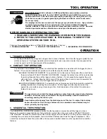
Страница 7: ...ontact trip until the nose touches the work surface and then pull the trigger to drive a fastener Do not press the tool against the work with extra force Instead allow the tool to recoil off the work surface to avoid a second unwanted fas tener Remove your finger from the trigger after each operation B RAPID FASTENER OPERATION To operate the tool in this manner hold the tool with the contact trip ...

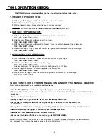
Страница 8: ...gger The trigger must return to the trigger stop on the frame C Pull the trigger and press the contact trip against the work surface THE TOOL MUST NOT CYCLE D With finger off the trigger press the contact trip against the work surface Pull the trigger THE TOOL MUST CYCLE IN ADDITION TO THE OTHER WARNINGS CONTAINED IN THIS MANUAL OBSERVE THE FOLLOWING FOR SAFE OPERATION Use the STAN TECH pneumatic ...

Страница 9: ...d hoses or from the effects of dirt and water in the system Restricted air flow will prevent the tool from receiving an adequate volume of air even though the pressure reading is high The results will be slow operation misfeeds or reduced driving power Before evaluating tool problems for these symptoms trace the air supply from the tool to the supply source for restrictive connectors swivel fittin...

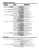
Страница 10: ...lace quick disconnect fittings Worn piston O ring Replace O ring check driver Tool dry lacks lubrication Use STAN TECH Air Tool Lubricant Damaged pusher spring Replace spring Low air pressure Check air supply system to tool Loose magazine nose screws Tighten all screws Fasteners too short for tool Use only recommended fasteners Bent fasteners Discontinue using these fasteners Wrong size fasteners ...

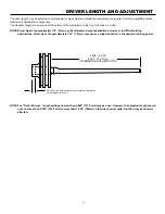
Страница 11: ...ications However in difficult driving applications driver wear of approximately 1 16 1 5mm may cause a slight reduction in the apparent driving power DRIVER LENGTH AND ADJUSTMENT NOTE For Flush Driving length settings shorter than 5 808 147 5mm may be used However the adjusted length should never be less than 5 625 142 8mm or more than 5 828 148mm otherwise normal nailer function may be adversly a...

Отзывы: