ASSEMBLY INSTRUCTIONS
11
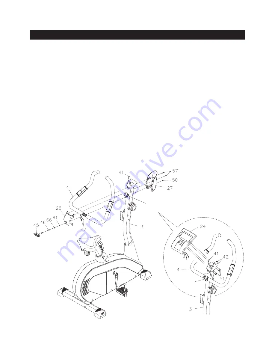
STEP 8
Place the
HANDLEBAR(4)
into the
CLIP
on the
UPRIGHT(3).
Refer to the detail view A. Run the
PULSE
SENSOR WIRES(42)
through the holes on both sides of the
UPRIGHT(3)
and come out from the square
opening on the top.
STEP 9
Install two AAA batteries into the
METER(24),
the batteries are not included. See page 16 for detailed
battery installation instructions. Plug the
CONNECTION WIRE(41)
and
PULSE SENSOR WIRES(42)
into
the
METER(24),
and push the excess wires back into the
UPRIGHT(3).
Place the
METER(24)
on the plate
on the
UPRIGHT(3)
and secure with
ROUND HEAD SCREWS(M5x0.8x10mm)(51).
NOTE:
Be careful not to damage the wires when attaching the
METER(24)
to the
UPRIGHT(3).
STEP 10
Attach the
FRONT HANDLEBAR COVER(27)
to the
UPRIGHT(3)
with
ROUND HEAD SCREW(M5x0.8x16mm)
(50).
Bolt the
FRONT HANDLEBAR COVER(27)
and the
HANDLEBAR COVER(28)
together with
ROUND
HEAD SCREWS(M4x20mm)(57).
Lock the
HANDLEBAR(4)
in position with the
T KNOB(45), PRESSING
SPACER(46), LOCK WASHER(M8)(66),
and
SMALL WASHER(M8)(61).
Clip
Clip
A.
Содержание A150-104
Страница 24: ...PRODUCT PARTS DRAWING 24 FRONT BACK...


