background image

Istruzioni Instructions Anleitungen


22

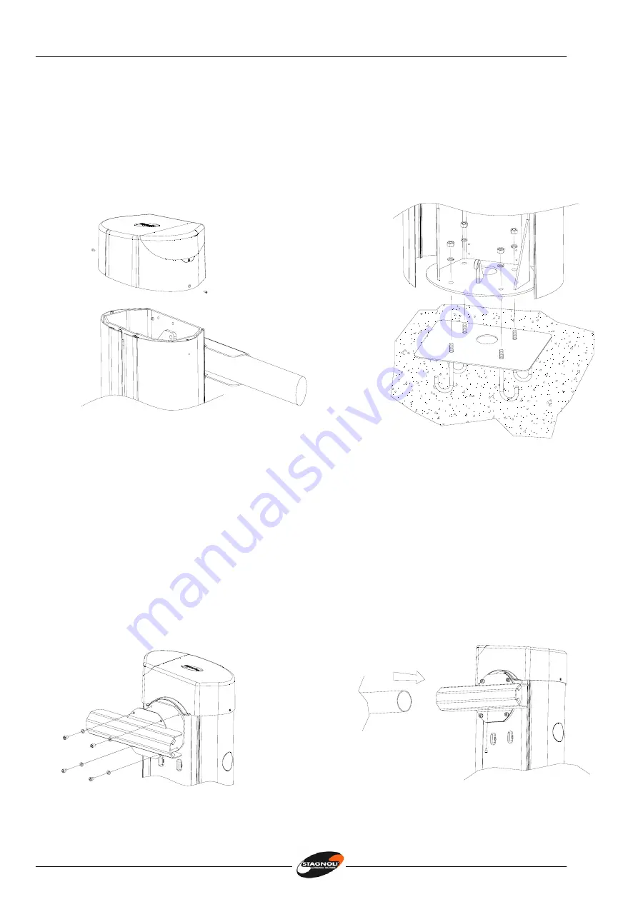
Befestigung der Schranke 


Durch die Lösung der Schrauben die obere Abdeckhaube abnehmen (Abb. 3). 


Die Gehäuseflügel öffnen; die Schranke auf der Fundamentplatte aufstellen, dabei die 
Gewindebolzen den vorbereiteten Bohrungen anpassen; die Schranke durch 

Aufschrauben der Mutter M10 auf die entsprechen Bolzen, befestigen (Abb.4). 


                     Abb.  3                                                                                     Abb.  4 
 

Befestigung des Schrankenbaums 


Den Bügel der Gleitbacke fixieren, ohne die Schrauben festzustellen (Abb. 5).


Den 80mm Ø runden Schrankenbaum in den Bügel einführen, dabei das richtige Ende in 
den Schlitz stecken. Den Schrankenbaum bis zum Anschlag einführen. Mit 4 Schrauben M8 
(Abb. 6) und den runden Schrankenbaum mit der M6x8 Schraube befestigen. 


Verbindungskupplung auf der Stange mit einem Durchmesser von 80 mm anbringen und 
die Stange von 60 mm Durchmesser einführen. 


Alles mit den entsprechenden Schrauben feststellen.


Abb.  5                                                                 Abb.  6


Содержание DAPHNE 6

Страница 1: ...Istruzioni Instructions Anleitungen 1 I Barriera GB Barrier D Schranke F Barri re DAPHNE 6...

Страница 2: ...ppositamente per gestire il controllo del passaggio di veicoli quindi vietato utilizzare il prodotto per scopi diversi da quelli previsti o in modo improprio Utilizzare componenti originali La ditta S...

Страница 3: ...oni Instructions Anleitungen 3 DAPHNE 24 V Impianto tipo 230V 50Hz 3x1 5 Selettore a chiave o digitale Barriera Fotocellula a colonna Polifemo Sensore magnetico Interruttore onnipolare Lampeggiante in...

Страница 4: ...NE 6 Alimentazione 230V 50Hz Assorbimento motore A 5 Alimentazione motore 24V Potenza motore max 120W Tempo di apertura sec 10 Temperatura operativa C 20 60 Ciclo di lavoro intensivo Livello di protez...

Страница 5: ...istiche idonee a garantire una sufficiente tenuta del plinto di cemento in cui sar collocata la piastra di fondazione Prevedere il passaggio cavi come da impianto tipo Il passaggio cavi situato in pos...

Страница 6: ...ssare la barriera avvitando i dadi M10 sui rispettivi tiranti Fig 4 Fig 3 Fig 4 Fissaggio asta Fissare la staffa porta asta senza avvitare a fondo le 4 viti Fig 5 Infilare l asta di diametro 80 mm in...

Страница 7: ...iorario come indicato in Fig 7 Fig 7 Per invertire il senso di apertura spostare la centrale di comando 1 spostare la molla nella posizione opposta Fig 8 e invertire il collegamento del motore elettri...

Страница 8: ...met corsa 45 Fig 10 45 Fig 10 Procedere con la programmazione seguendo le istruzioni della centrale di comando e dopo aver effettuato la programmazione completa aggiustare le posizioni di fine corsa...

Страница 9: ...o bilanciare nuovamente l asta regolando il tirante filettato vedi Fig 10 Verifica del corretto allineamento dell asta Verifica del tensionamento della catena di trasmissione Ogni 500 000 manovre eseg...

Страница 10: ...manage the access control of vehicles It is therefore forbidden to use the product for different reasons other than those foreseen in this manual It is forbidden to use it for any other purposes or i...

Страница 11: ...Istruzioni Instructions Anleitungen 11 Blinker DAPHNE 230V 50Hz 3x1 5 Digital or key selector Barrier Polifemo clolumn type photocell Magnetic loop Omnipolar switch...

Страница 12: ...Details DAPHNE 6 Power Supply 230V 50Hz Current absorbed Motor A 5 Motor Power Supply 24V Maximum Power Max 120W Opening Time sec 10 Operating Temperature C 20 60 Duty Cycle intensive IP Protection 4...

Страница 13: ...ure that the ground is ideal for holding the cement base in which the foundation plate will be mounted Make sure to foresee the passage of the cables as in the ideal set up The cable passage is situat...

Страница 14: ...rything in place with the M10 nuts Fig 4 Fig 3 Fig 4 Fixing in the aluminium bar Fix down the bar holder bracket without wholly tightening down the screws Fig 5 Slide the 80mm diameter barrier arm int...

Страница 15: ...rier is in an anticlockwise direction as in Fig 7 Fig 7 To invert the opening direction of the arm move the spring to the opposite position Fig 8 and invert the connection of the electric motor to the...

Страница 16: ...10 45 Fig 10 Proceed with the programming of the control panel following the specific electrical instructions and after having carried out the complete programming regulate the position of the arm s l...

Страница 17: ...alance the arm adjusting the screwable rods see Fig 10 Check the correct alignment of the arm Verifying the tension on the transmission chain Every 500 000 manoeuvres carry out a revision of the follo...

Страница 18: ...igens f r die Regelung von Fahrzeugdurchfahrten entwickelt eine zwecksentfremdete oder nichtsachgem e Verwendung des Produktes ist daher untersagt Es sind ausschlie lich Originalteile zu verwenden Die...

Страница 19: ...uzioni Instructions Anleitungen 19 DAPHNE 24 V Anlagesystem Blinkleuchte Schl ssel oder Digitalschalter Schranke Lichtschranke am Pfosten Poliferno Magnetischer Sensor Allpoliger Schalter 230V 50Hz 3x...

Страница 20: ...nische Daten DAPHNE 6 Stromversorgung 230V 50Hz Stromaufnahme A 5 Betriebsspannung 24V Motorleistung max 120W Laufzeit ffnung Sek 10 Betriebstemperatur C 20 60 Einschaltdauer intensiv Schutzgrad IP 44...

Страница 21: ...die erforderliche Tiefe des Betonfundaments auf der die Fundamentplatte aufgesetzt wird zu gew hrleisten Eine Kabelf hrung ist wie f r dieses Anlagetyp vorgesehen vorzusorgen Die Kabelf hrung verl uft...

Страница 22: ...igen Abb 4 Abb 3 Abb 4 Befestigung des Schrankenbaums Den B gel der Gleitbacke fixieren ohne die Schrauben festzustellen Abb 5 Den 80mm runden Schrankenbaum in den B gel einf hren dabei das richtige E...

Страница 23: ...Uhrzeigersinn erreicht so wie dem Abb 7 zu entnehmen ist Abb 7 Will man die ffnungsrichtung umkehren so ist die Federf hrung in entgegengesetzte Stellung zu bringen Abb 8 Der Motoranschluss an der Ste...

Страница 24: ...alten k nnen Abb 10 45 Abb 10 Mit der Programmierung fortfahren dabei den Anweisungen der Steuerung Folge leisten Nach der Beendigung der gesamten Programmierungsverfahren ist die Position der Endansc...

Страница 25: ...erpr fen wenn n tig die Stange noch einmal ausgleichen daf r die Gewindebolzen justieren vgl Abb 10 Die korrekte Ausrichtung der Stange ist zu berpr fen Die Spannung der bertragungskette ist unbedingt...

Страница 26: ...HNE a t r alis e express ment pour g rer le contr le du passage des v hicules il est d fendu alors d utiliser le produit pour les buts divers des ceux pr vus ou du mode impropre Utiliser pi ces origin...

Страница 27: ...Istruzioni Instructions Anleitungen 27 DAPHNE 24 V Dispositif type Lampe S lecteur cl ou digital Barri re Photocellule colonne Polifemo Senseur magn tique Interrupeteur omnipolaire 230V 50Hz 3x1 5...

Страница 28: ...Alimentation 230V 50Hz Absorption moteur A 5 Alimentation moteur 24V Puissance moteur max 120W Temps d ouverture sec 10 Temperature op rationnelle C 20 60 Cycle de travail intensivo Niveau de protecti...

Страница 29: ...ristiques similaires et garantir une suffisante tanch it de la base du ciment dans laquelle la plaque de fondation va tre pla e Pr voir le passage pour les c bles comme dans le cas de dispositif type...

Страница 30: ...M10 sur les tirants relatifs Fig 4 Fig 3 Fig 4 Fixation de barre Fixer la barre porte barre sans visser fond les vis Fig 5 Introduire la lisse 80 mm dans le support du c t oppos au tampon de fermeture...

Страница 31: ...u sens contraire au mouvement de l horloge comme indiqu en Fig 7 Fig 7 Pour invertir le sens d ouverture d placer le ressort en position oppos e Fig 8 et faire invertir la connexion du moteur lectriqu...

Страница 32: ...10 45 Fig 10 Proc der avec la programmation respectant les instructions de la centrale de commande et apr s avoir effectu la programmation compl te ajuster les positions de fin de course de la barre...

Страница 33: ...a barre regulant le tirant ray voire Fig 10 V rifier l alignement correct de la barre V rification de degr de tension de la cha ne de transmission Tous les 500 000 manoeuvres effectu es il faut condui...

Страница 34: ...en 34 DAPHNE 6 49 48 44 42 43 50 51 52 53 54 56 57 58 59 59 55 62 63 64 60 61 65 66 68 67 69 70 71 72 73 74 36 1 2 3 4 5 6 7 8 12 10 11 9 9 14 13 15 16 17 18 19 20 21 22 24 23 25 26 27 28 29 30 32 33...

Страница 35: ...1A852 25 Pignone x 5 16 Z16 1 X61A954 26 Dado fiss Motoridutt M8 6 X61A11 27 Dado spessore M10 4 X61A923 28 Vite M8 x 120 4 X61A924 29 Antivibrante d 50 mm 2 X61A912 30 Dado M10 autobloccante 2 X61A25...

Страница 36: ...Istruzioni Instructions Anleitungen 36 REV 1 10 07 Stagnoli s r l Via Mantova traversa 1 105 A B Lonato Bs Italia Tel 39 030 913 9511 Fax 39 030 913 9580 www stagnoli com...

Отзывы: