


UM1990
System overview
DocID028662 Rev 2
3/27
1
System overview
The system STM32F103 microcontroller functions as the bridge between various
communications modules. The Wi-Fi, Bluetooth and Sub GHz modules are connected via
UART to the STM32, while the NFC transceiver module is connected via SPI.
The board requires a 5 V, 1 A wall adapter for power, and a USB Micro B-Type connector
can interface the board to the PC.
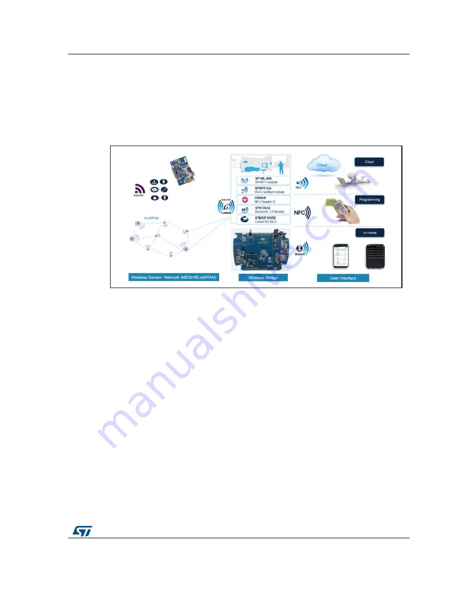
Figure 3: Wireless Bridge WiFi/NFC/BT/RFSubGHz scenario
When the board is connected to a PC via USB, Wi-Fi configuration parameters and the
mesh node configuration can be programmed through a PC GUI application and debug log
messages can be collected through the same GUI.
The sensor data from any node in the mesh network (6LoWPAN) is accessible through the
android application as well as through a Cloud based application at the website
(http://cloudbridge.azurewebsites.net/) using the Wi-Fi interface.
The board is powered through a 5 V, 1 A wall adapter, and the status of various
communication interfaces is indicated by five LEDs on the board.
The RF nodes that can be connected by RF SubGHz 6LoWPAN in the Wireless Bridge are
STEVAL-ISTEVAL-IDI002V2.
The Wireless Bridge board are embedding the following RF modules:
Sub-GHz RF module: SP1ML-868
868 MHz ETSI-certified module
Based on sub-GHz SPIRIT1 transceiver, STM32L1 ULP MCU and balun (BALF-
SPI-01D3)
Chip antenna
Simple AT command
Wi-Fi module: SPWF01SA.11
2.4 GHz IEEE 802.11 b/g/n Wi-Fi
Pre-certified RF module (FCC, IC, CE)
Integrated TCP/IP
AT commands
TLS/SSL for end-to-end security
Over-the-air firmware updates