


7.16
CAN FD
7.16.1
Description
The STM32U575I-EV Evaluation board supports one CAN FD compliant with ISO-11898-1 version 2.0 parts A
and B. The CN22 DB9 male connector is available as a CAN
‑
FD interface.
7.16.2
Operating voltage
A 3.3 V CAN transceiver is fitted between the CN22 connector and the CAN
‑
FD controller port of
STM32U575AII6Q.
In this configuration, the CAN
‑
FD interface is compatible with the MCU voltage range, from 1.8 to 3.6 V (Low
voltage 1.71 V does not fit with the CAN transceiver specification).
7.16.3
CAN
‑
FD interface
The JP26 jumper allows selecting one among the high-speed, standby, and slope
‑
control modes of the CAN
transceiver.
The JP28 jumper can fit a CAN termination resistor (R81). The JP27 and JP29 are used to connect the CAN
transceiver to STM32U575AII6Q. This helps to select the muxing for the CAN
‑
FD I/O which is shared with other
interfaces.
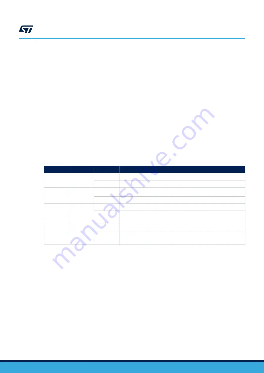
describes the hardware configuration for the CAN
‑
FD interface.
Table 31.
Hardware I/O configuration for the CAN
‑
FD interface
I/O
Jumper
Setting
Configuration
-
JP26
JP26[1-2]
CAN transceiver operates in high-speed mode.
JP26[2-3]
CAN transceiver is in standby mode.
-
JP28
ON
Termination resistor fitted on CAN physical link
OFF
No termination resistor on CAN physical link
PB8
JP29
ON
PB8 is used from STM32U575AII6Q terminal as CAN_RX.
OFF
PB8 is not used for the CAN transceiver.
PB8 can be used for UCPD or Ext-MEMS.
PB9
JP27
ON
PB9 is used from STM32U575AII6Q terminal as CAN_TX.
OFF
PB9 is not used for the CAN transceiver.
PB9 can be used for UCPD.
1. The default configuration is shown in bold.
STM32U575I-EV
CAN FD
UM2854
-
Rev 1
page 47/105