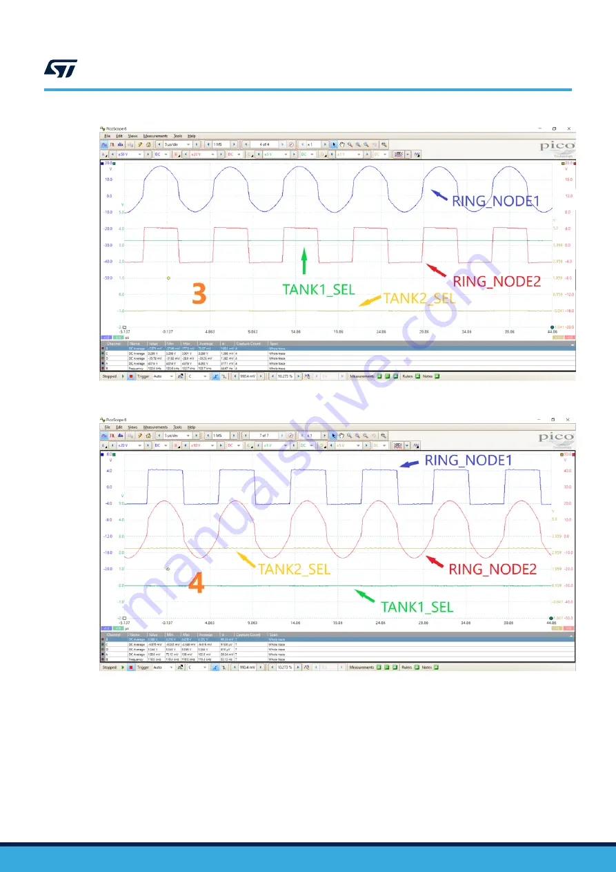
Figure 8.
Coil 1 in full-bridge mode
Figure 9.
Coil 2 in full-bridge mode
4.4
STSC waveform
The STSC protocol supports a higher power transfer. The figure below shows the typical waveform.
TN1399
-
Rev 1
page 9/26
Страница 1: ...hardware a high resolution main PWM controller a dedicated Qi communication modulator and demodulator a USB PD controller a buck DC DC a charge pump The STDES 50W2CWBC is a fully assembled reference...
Страница 2: ...nce magnetic resonance capacitive coupling radio frequency laser charging etc The most popular mechanism is the magnetic inductive that follows the Qi standard defined by the Wireless Power Consortium...
Страница 3: ...converter supports an AC voltage 100 V the coil switcher alternatively switches the two LC tanks for coils alternatively into high voltage the STLINK V3MINI interface with SWD for firmware debug and...
Страница 4: ...ctive wireless charger power receiver for 50 W applications or 70 W applications STWLC88 or STWLC98 Yes C6 Wall adapter USB PD wall adapter No C7 USB Type C cable 4 A or 5 A cable No 3 2 Procedure To...
Страница 5: ...6 Test the power transfer switching The oscillation waveform appears in the activated RING_NODE while the switching waveform appears in another inactive RING_NODE The switching waveform should be off...
Страница 6: ...ure 4 Typical startup waveform power on sequence 4 2 Presence detection waveform Once the STWBC2 HP power up is ready you can check the presence detection waveform at RING_NODE1 triggered by TANK1_SEL...
Страница 7: ...ne waved while the RING_NODE2 is off see Figure 6 2 Put the Rx coil on Tx coil 2 and set the Rx output to 5 V The RING_NODE2 appears sine waved while the RING_NODE1 is off see Figure 7 3 Put the Rx co...
Страница 8: ...Figure 6 Coil 1 in half bridge mode Figure 7 Coil 2 in half bridge mode TN1399 Power transfer switching waveform TN1399 Rev 1 page 8 26...
Страница 9: ...1 in full bridge mode Figure 9 Coil 2 in full bridge mode 4 4 STSC waveform The STSC protocol supports a higher power transfer The figure below shows the typical waveform TN1399 STSC waveform TN1399 R...
Страница 10: ...n waveform The firmware can route the demodulation result V I to a GPIO which should be close to the Rx modulation waveform The figure below shows the typical waveform Figure 11 ASK demodulation frame...
Страница 11: ...coil reference design should be close to the LCR meter The table below shows the test results Table 7 Q factor accuracy test with RMB coins DTU One Yuan 50 cents 10 cents LCR 11 7 18 1 29 4 Coil 1 11...
Страница 12: ...A6 D 1 A7 D 1 A8 A9 A10 A11 G ND1 G ND G ND2 G ND G ND3 G ND B6 G ND4 G ND SH1 G ND SH2 G ND SH3 G ND SH4 G ND J100 632723300011 R107 0 R R106 0 R R103 NP C100 X7R 50V 100NF D104 BAT30KFILM NTR4003NT1...
Страница 13: ...F C202 X5R 50V 470NF C215 X7R 25V 100NF C217 X7R 25V 100NF C218 X7R 25V 100NF C223 X7R 25V 100NF C224 X7R 25V 100NF C228 C0G 50V 33PF C220 X7R 100V 1NF R220 0 R NTC R211 47 K R210 150 K R213 470 K C22...
Страница 14: ...3 Q300 STL20N6F7 R300 0 010R 2W C312 NP C313 C0G 50V 1NF L300 3 3uH R306 10 R C315 X7R 50V 10NF R307 10 R C309 X7R 50V 100NF C314 X7R 50V 10NF C310 50V COG 1NF R410 100 K D400 10V G D S 5 4 1 6 7 8 2...
Страница 15: ...4 DNP 1206 C404 X7S 100V DNP R420 DNP 1206 C401 X7S 100V DNP R416 10K R421 10K C402 C0G 50V 1NF D401 1N4148WS C418 X7R 50V 10NF R422 47K R423 10K R425 10K C423 C0G 50V 1NF D402 1N4148WS C425 X7R 50V 1...
Страница 16: ...Capacitors Murata or generic GRM155R60J475ME47 8 1 C202 470 nF 0402 35 V 10 X5R SMD Capacitor Kemet or generic C1005X5R1V474M050BC 9 2 C221 222 8 2 PF 0402 50 V 5 C0G SMD Capacitors Kemet or generic C...
Страница 17: ...1 R423 R425 10K 0402 1 16 W 5 SMD Resistors Yageo or generic RC0402JR 0710KL 26 2 R203 R210 150 K 0402 1 16 W 5 SMD Resistors Yageo or generic RC0402JR 07150KL 27 3 R212 R225 226 2 2 R 0402 1 16 W 5 S...
Страница 18: ...1 6 SMD crystal NDK NX2016SA 16MHz EXS00A CS06655 49 1 J100 632723300011 CON_USB_C_632723300011 USB TYPE C_632723300011 Wurth Elektronik 632723300011 50 1 J101 FTSH 107 01 L DV K A CON_FTSH 107 01 L D...
Страница 19: ...arger transmitters ST STWBC2 HP 62 2 D203 D209 0603 Green LEDs Wurth Elektronik 150060VS75000 63 1 D202 0603 Red LEDs Wurth Elektronik 150060RS75000 64 2 R235 236 100 R 0402 1 16 W 5 SMD Resistors Yag...
Страница 20: ...f the two coils The Rx output could be from 5 V to 20 V by the ST Super Charge proprietary protocol STSC The ASK demodulation works well The Q factor estimation by either of the two coils is close to...
Страница 21: ...d tests specifically described in the published documentation for the specified reference design STMicroelectronics may correct enhance improve its reference designs for future development STMicroelec...
Страница 22: ...Revision history Table 8 Document revision history Date Revision Changes 01 Mar 2022 1 Initial release TN1399 TN1399 Rev 1 page 22 26...
Страница 23: ...Presence detection waveform 6 4 3 Power transfer switching waveform 7 4 4 STSC waveform 9 4 5 ASK demodulation waveform 10 4 6 Q factor accuracy test 11 5 Schematic diagrams 12 6 Bill of materials 16...
Страница 24: ...ternal voltage range 4 Table 4 Power on LED status 5 Table 5 Presence detection specifications 5 Table 6 Level of the STSC power supplies 5 Table 7 Q factor accuracy test with RMB coins 11 Table 8 Doc...
Страница 25: ...half bridge mode 8 Figure 7 Coil 2 in half bridge mode 8 Figure 8 Coil 1 in full bridge mode 9 Figure 9 Coil 2 in full bridge mode 9 Figure 10 Power automatic boost 5 20 V 10 Figure 11 ASK demodulatio...
Страница 26: ...ts and ST assumes no liability for application assistance or the design of Purchasers products No license express or implied to any intellectual property right is granted by ST herein Resale of ST pro...