ST7540 FSK powerline transceiver description
AN2451
10/55
Doc ID 12791 Rev 3
3
ST7540 FSK powerline transceiver description
ST7540 transceiver uses frequency shift keying (FSK) modulation to perform a half-duplex
communication on a powerline network. It operates from a 7.5 to 13.5 V single supply
voltage (Vcc) and integrates a power amplifier (PA), which is able to drive low line
impedance, and two linear regulators providing 5 V and 3.3 V.
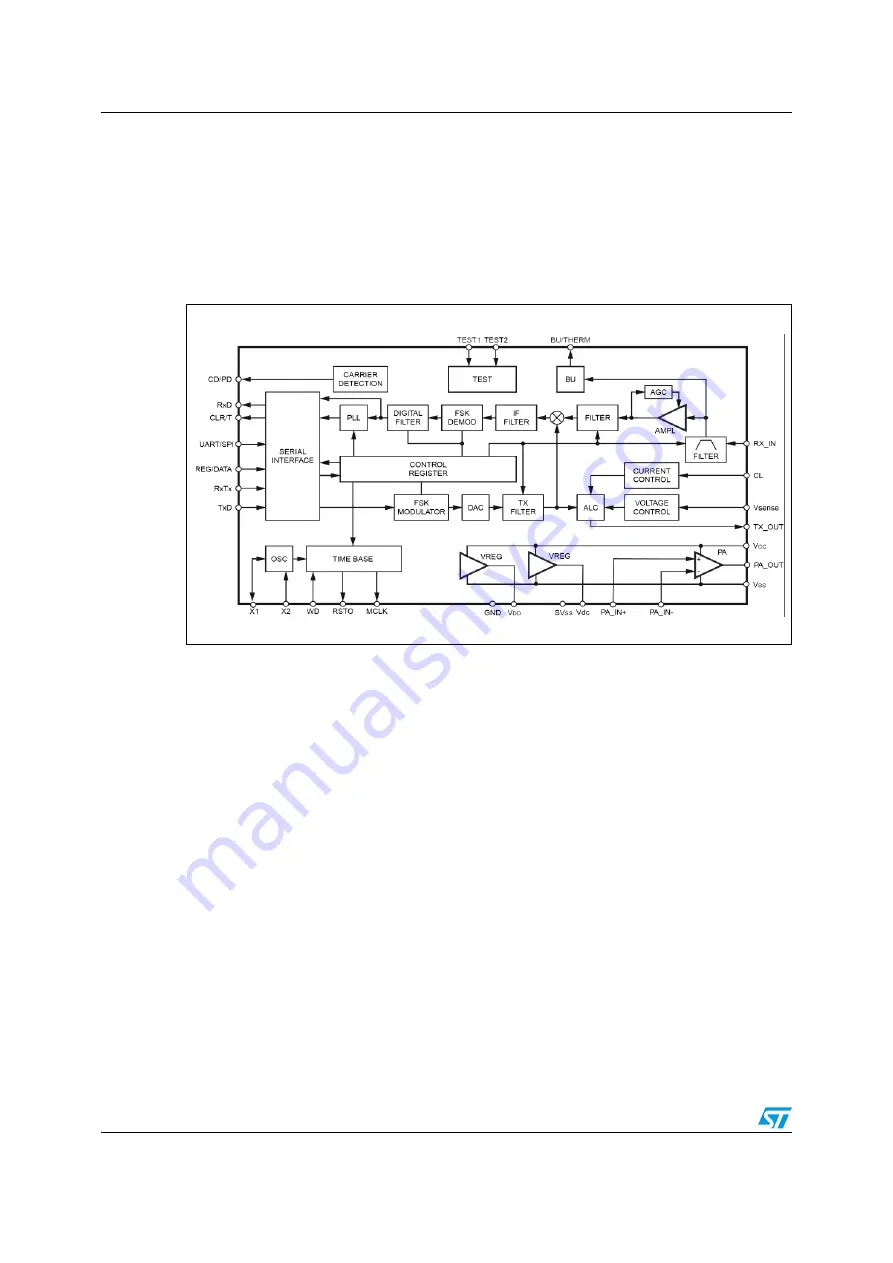
Figure 3.
ST7540 Transceiver block diagram
The ST7540 can communicate using eight different communication channels (60, 66, 72,
76, 82.05, 86, 110, 132.5 kHz), four baud rates (600, 1200, 2400, 4800) and two deviations
(1 and 0.5). Additional functions are included, such as watchdog, automatic control on PA
output voltage and current, carrier/preamble detection and band-in-use signaling,
transmission time-out, and thermal shutdown.
The transceiver, which is dedicated only to physical communication, operates with a
microcontroller whose aim is to manage the communication protocol stack. A reset output
(RSTO) and a programmable clock (MCLK) can be provided to the microcontroller by the
ST7540 in order to simplify the external logic and circuitry.
The host controller can exchange data with the transceiver through a serial interface,
programmable to operate either in UART (CLR/T data clock not used) or in SPI mode.
Communication on the power line can be either synchronous or asynchronous to the data
clock that is provided by the transceiver at the programmed baud rate.
When in transmission mode (i.e. RxTx line at low level), the ST7540 samples the digital
signal on the TxD line at the programmed baud rate and modulates it in a FSK sinusoidal
output on the Tx_OUT line. This signal is then externally fed into the power amplifier to add
current capability. The power amplifier can also introduce gain and active filtering to the
signal, just using few external passive components. The resulting signal on the PA_OUT line
is coupled to the power line.
When in receiving mode (i.e. RxTx line at high level), an incoming FSK signal on the Rx_IN
line is demodulated and the digital output is available for the microcontroller on the RxD pin.
Содержание ST7540
Страница 47: ...AN2451 Application ideas Doc ID 12791 Rev 3 47 55 Figure 47 Line coupling interface for 110 kHz channel...
Страница 48: ...Application ideas AN2451 48 55 Doc ID 12791 Rev 3 Figure 48 Line coupling interface for 132 5 kHz channel...
Страница 51: ...AN2451 Board layout Doc ID 12791 Rev 3 51 55 Appendix A Board layout Figure 49 PCB layout component placing...
Страница 52: ...Board layout AN2451 52 55 Doc ID 12791 Rev 3 Figure 50 PCB layout top view...
Страница 53: ...AN2451 Board layout Doc ID 12791 Rev 3 53 55 Figure 51 PCB layout bottom view...


