________________________________________________________________________________________________________________________________________________________________________________________________________________________
07-01-02-02-E-V0605.DOC
Product Manual Type:
NEB/3U
11
7 Adjustments
7.1
The ballast power is adjusted in production!
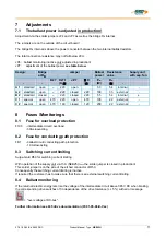
Adjustment via the solder jumpers JP4 and JP7 as well as the bridge R
B
internal.
The jumpers are on the outside of the circuit board!
The bridge R
B
internal is above the power connector between the two internal ballast resistors.
The total connection resistance may not fall below 20
Ω
.
JP4: ballast monitoring inactive only adjusted in production!
JP7:
adjustment of the ballast power
see table below
Design:
Bridge
at RB
Jumper
Ballast
power
Resistance
value
Supply unit
with sep. fan
R27
R27.1
JP 7
Σ
R
P
w
R
w
-
-
(K
Ω
)
(
Ω
)
(W)
(
Ω
)
-
A 1
standard open
∞
220 open
30 54 internal
-
A 2
standard open
∞
220 closed 220 100 33
external
-
B 2
standard closed
∞
220 closed 220 55 54 internal
x
C 1
special open
470
220 open 470 100 22
external
-
C 2
special open 470 160 closed 120 200
22 external
-
8 Fuses
/Monitorings
8.1
Fuse for overload protection
F100
- intermediate circuit / overload
- 30A slow-acting
8.2
Fuse for conducting path protection
FB1
- ballast circuit/ conducting path
protection
- 10 A slow-acting
8.3
Switching current limiting
Surge-Gard R50 for switching current limiting
With operation of the supply unit via 15 A (NEB25) I
nenn
the solder jumper is closed in production!
This solder jumper is on the side of the etched conductor of R50.
Consequently the switching current limiting is inactive.
If required the customer has to make sure that there is an external switching current limiting.
8.4 Ballast
monitoring
If the returned electric energy lets rise the voltage of the intermediate circuit above 385 V DC when braking,
the corresponding drive switches off in dependence of the drive tolerance (+/- 5 %) with error message
= "over voltage at DC-bus".
Further information see 635 drive documentation (07-01-05-06-D-Vxx )


