


24
2 Operation
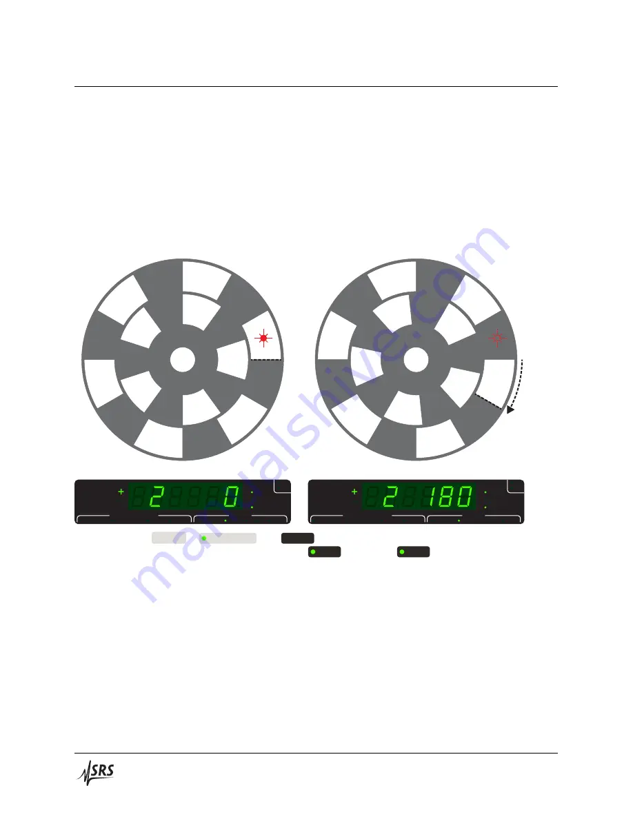
optical beam. Note that a change of 180
°
opt when controlling the outer
track of this 6‑slot blade corresponds to a 30
°
mech rotation.
Because the angular orientation of the chopper blade in
°
opt spans the
range from [0
°
,
𝑛
slots
×
360
°
), the front‑panel display of the phase setting
in
shutter mode
is given as a combination of slot number
𝑁
[0,
𝑛
slots
‑1]
and angle remainder
𝐷
[0
°
, 360
°
), such that:
Phase
(°) = 𝑁 × 360° + 𝐷(°)
(2.1)
180°opt
(30°mech)
0
1
2
3
4
5
0
1
2
3
4
5
USB
ERR
Hz
deg
Multiplier
Rel
Outer Slots
Inner Slots
Int Freq
Phase
VCO FS
n
m
Frequency Monitor
Settings
Shaft
Source
USB
ERR
Hz
deg
Multiplier
Rel
Outer Slots
Inner Slots
Int Freq
Phase
VCO FS
n
m
Frequency Monitor
Settings
Shaft
Source
Figure 2.7:
With
Source
=
Internal Freq
and
Int Freq
= 0 Hz, the SR542 enters
shutter mode
, which keeps the
chopper blade in a fixed position as determined by the
Phase
setting. The
Phase
display in this mode presents
an integer slot number
𝑁
and angle
𝐷
, where the phase setpoint = (
𝑁×
360
°
) +
𝐷
. LEFT:
𝑁 = 2
,
𝐷 =
0
°
. RIGHT:
𝑁 = 2
,
𝐷 =
180
°
.
The shaft encoder installed on the chopper head has a mechanical res‑
olution of 0.9
°
mech. In
shutter mode
, rotations less than that are not
achievable. In
chop mode
, the controller CPU uses timing information
from the shaft encoder signals to achieve more precise phase control.
SR542 Precision Optical Chopper


