


MODEL SR520
ASSEMBLY INSTRUCTIONS
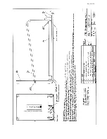
(refer to figure on next page)
1.
Insert mast (7) into mast collar of base assembly (6) as shown.
2.
Remove the 4 set screws from the base collar and apply loctite to all set screws.
3.
Make sure the mast is seated frimly in the base unit then reinstall the set screws and tighten
against the mast.
4.
Slide the readout (5) cable down the mast (7) and pull out through the base (6).
5.
Place the readout (5) on to the top of the mast (7) as shown
6.
Remove the 4 set screws from the readout collar and apply loctite to all set screws.
7.
Make sure the readout (5) is seated frimly in the mast (7) and the readout and base assambly
are lined up square and level to each other then reinstall the set screws and tighten against
the mast.
8.
Lay system on it's side and remove the cable clamp (see drawing on next page) from the
base.
9.
Attach the readout cable connector to the mating connector in the base.
10.
IMPORTANT: REINSTALL THE CABLE CLAMP - Set the readout cable in to the grove under
the cable clamp and reinstall the cable clamp leaving just enough slack to eleviate any tension
on the connector. Make sure to apply loctite to cable clamp screws. Slide the excess cable
back up into the mast.
11.
Remove the 2 screws from the battery compartment cover and install 6 "C" cell batteries as
indicated on the cover diagram. Replace the cover.
OPTIONAL HANDRAILS -
1.
Apply loctite to all screws provided with handrails.
2.
Attach the handrails (2) to the bottom side of the readout with 2 screws and split lock washers
each side (3.4).
3.
Attach the bottom of the handrails to the base as shown (3,4) with 1 screw and split lock
washer each side.
OPTIONAL HEIGHT BAR -
1.
Remove the clamp screw on the rear tab of the readout (5).
2.
Slide the height bar (1) down through the readout clamp and seat firmly into the base
3.
Apply loctite to all of the set screws.
4.
Make sure that the height bar is square to the base then tighten all set screws.
If you have any questions or problems please call 1(800)654-6360 for assistance. Our
technicians will be glad to help you.
Rev. 021126
page 10
Содержание SR520
Страница 11: ...Rev 021126 TURN KNOB TO ACCESS BATTERIES...
Страница 12: ...Rev 021126...


