


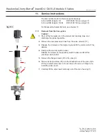


11. Service Instructions
The item numbers refer to the spare parts drawings
Inch and DIN designs: D4
RN 500.047.02 (see page 27)
Inch and DIN designs: D4 SL RN 501.047.02 (see page 30)
For Disassembly/Assembly tools, see chapter 13.
11.2. Removal of product-wetted parts
1.
Release the lower safety nut (15). Hold the lower shaft (3) with an
SW17 wrench to keep it from turning.
2.
After removing the nut (15), lift off the lower shaft (3).
3.
Place the point of the tool along the side of the seat seal (10) and pull it
out of the groove. Take the quad ring (14) out of the groove.
4.
Remove the operating cam from the guide rod (7).
5.
In order to take off the adapter, remove the 4 screws.
6.
Remove the stop screw (23).
7.
Take the guide rod (7) out through the top of the actuator.
8.
Remove the operating cam at the upper shaft.
9.
Unscrew the safety nut (24). Hold up the lock washer (25) with a SW30
key to keep it from turning. Remove the lock washer.
10.
Lift off the actuator (17) with yoke (6).
11.
Slide the shaft bearing (4) over the balancer of the upper valve shaft
(2).
12.
Remove the shaft seal (11) and piston rings (12) from the grooves.
13.
Removing the seals in the upper shaft
Place the point of the tool along the side of the seat seal (10) and
middle seal (9) and pull them out of the groove. Take the quad ring (14)
out of the groove.
14.
Removing the lower shaft seal from the housing
Place the point of the disassembly tool along the side of the shaft seal
(11) and pull it out through the top of the housing (1).
15.
Place the metal point of a hook in the gap of the guide ring (12). Slightly
turn the hook to lift the guide ring (12) out of the groove and housing
(1).
operating cam
upper shaft
23
7
25
24
17
6
12
2
detail x
3
15
12
11
fig. 11.2.
operating cam
lower shaft
4 screws
1
11
4
detail x
10
9
10
14
19
WCB_D4_D4SL_sch5_US.indd
D4 / D4 SL Schedule 5 Series
Double Seat Mix Proof Valves
Instruction Manual: US - rev. 0
Waukesha Cherry-Burrell
®
brand D4 / D4 SL Schedule 5 Valves


