


1750
+
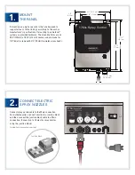
SPRAY CONTROLLER
3.
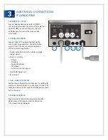
ADDITIONAL CONNECTIONS
IF APPLICABLE
1. REMOTE DUTY CYCLE
Connect Remote Duty Cycle cable to 4-20mA
connection on the panel. Once the unit is powered
up on the HMI you can set the duty cycle with
a 4-20mA signal to control the spray nozzles
cycle speed.
2. TRIGGER OR SENSOR
Connect cable to Trig connection that will be
used to start spray sequence. Available triggers
are as follows, the one used should be based
on the customer’s application.
•
Trigger cable (for use with customer-supplied
trigger signal)
•
Sensors including:
– Object
– Proximity
– Laser (short/long)
– Thru-beam
– Full spectrum color sensor
•
Hand-held trigger unit
•
Foot switch
3. AUX = NOZZLE AIR ON/OFF
The Aux/Nozzle Air electrical connection is used to actu-
ate the air solenoids in our air control panel. Connect the
cable from the air control panel to Aux/Nozzle Air connec-
tion on the panel.
4. TRIGGER INTERLOCK
Trigger Interlock controls the state of run/standby
mode. Connect the trigger interlock cable to the
T. int. connection on the panel.
2
3
4
1


