background image


56


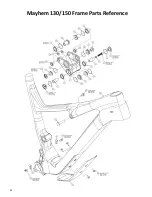
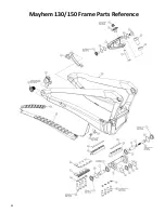
Mayhem 130/150 Frame Parts Reference


ITEM NO. 

PART NUMBER 

DESCRIPTION 

QTY. 

FS90102 

PIVOT AXLE CONE, DS LOWER 

FS90093 

PIVOT AXLE CONE, NDS 

FS80012 

WASHER, M6 HIGH COLLAR 

FS90147 

M6 X 38 TORX CAP SCREW 

FS80005 

BEARING, ENDURO 3802 LLU MAX 

FS90091 

PIVOT CAP, 15mm 

FS90090 

PIVOT AXLE CONE, DS UPPER 

FS90089 

M6 X 24 TORX CAP SCREW 

FS90088 

WASHER, 15mm 

10 

FS90168 

2020 MAYHEM PIVOT YOKE 

11 

FS90174 

2020 MAYHEM UPPER LINK 

12 

FS80002 

BEARING, ENDURO 1017 2RS MAX 

13 

FS90170 

2020 MAYHEM YOKE WASHER 

14 

FS90148 

2020 MAYHEM YOKE PIVOT AXLE 

15 

FS90149 

2020 MAYHEM UPPER LINK PIVOT AXLE 

16 

FS90172 

2020 MAYHEM 130 SHOCK YOKE 

17 

FS90166 

2020 MAYHEM SHOCK PIN, R 

18 

FS90048 

SHOCK PIVOT NUT 

19 

FS90171 

2020 MAYHEM OFFSET REDUCER 

20 

FS90167 

SHOCK REDUCER SPACER 

21 

FS90165 

2020 MAYHEM 130 SHOCK PIN, F 

22 

FS80003 

M6 X 11 TORX 

23 

FS80006 

M5 X 13 TORX 

24 

FS80007 

P-CLIP 

25 

FS90083 

BRAKE MOUNT 

26 

FS90161 

LEAF SPRING SCREW 32 

27 

FS90112 

LEAF SPRING SPOOLER, MAYHEM 

28 

FS90160 

LEAF SPRING SCREW 21.0 

29 

FS90158 

2020 MAYHEM LEAF SPRING CAP, F 

30 

FS90159 

2020 MAYHEM LEAF SPRING CAP, R 

31 

FS90150 

2020 MAYHEM UPPER PIVOT CAP 

32 

FS90157 

2020 MAYHEM SCREW COVER, F 

33 

FS90156 

2020 MAYHEM SCREW COVER R 

34 

FS80017 

O-RING 1.5 X 18 

12 

35 

FS80010 

O-RING 1.5 X 12 

36 

FS90155 

2020 MAYHEM COMPRESSION PLATE 

37 

FS90154 

2020 MAYHEM DT PROTECTOR 

38 

FS90153 

2020 MAYHEM STRUT PROTECTOR 

39 

FS90179 

2020 MAYHEM 130 FRONT TRIANGLE, L 

40 

FS90176 

2020 MAYHEM REAR TRIANGLE 

41 

SRAM 00.7918.089.000 

SRAM UDH RD HANGER 

42 

INC W/ RD HANGER 

SRAM UDH HANGER SCREW 

43 

FS90025 

PIVOT WASHER, MAIN 

44 

FS90172 

2020 MAYHEM COMPRESSION CAP 

45 

FS90059 

LEAF SPRING WASHER V2 

46 

FS90151 

2020 MAYHEM LEAF SPRING 

48 


SS PROTECTOR 

49 


CHAINSTAY PROTECTOR 

Содержание Mayhem 130

Страница 1: ...1 MY21 Mayhem 130 Frames Assembly Instructions and Maintenance Manual ...

Страница 2: ...ting Internal Dropper Seatpost Routing Rear Brake Hose Routing Rear Derailleur Cable Routing Bottom Bracket Installation Frame Disassembly Rear Derailleur Hanger Removal Replacement Rear Shock Removal Replacement Rear Triangle Removal Shock Yoke and Link Removal Pivot Bearing Replacement Main Pivot Bearing Replacement Rocker Link Bearing Replacement Frame Reassembly Rocker Link Reinstallation Rear...

Страница 3: ...sification standard for bicycle use outlined in document ASTM F2043 It is important to use any bicycle within its intended use classification to ensure rider safety equipment longevity and warranty coverage The Spot Mayhem 130 mountain bikes are classified within Level 3 of this standard 1 This is a set of conditions for the operation of a bicycle on a regular paved surface where the tires are int...

Страница 4: ...ockwise to slow the rebound counterclockwise to speed up Adjustment settings are referenced from full slow To adjust turn the red rebound knob clockwise until it stops then slowly unwind the knob while counting each time it clicks Spot recommended rebound settings based on air spring pressure Increase rebound speed if the bike feels rough and low on fast sections with successive bumps Decrease reb...

Страница 5: ...counting each time it clicks Spot recommended rebound settings based on air spring pressure Increase rebound speed if the bike feels rough and low on fast sections with successive bumps Decrease rebound speed if the bike feels bucky like riding a pogo stick on successive bumps Pressure psi Low Speed Rebound Setting clicks from full slow High Speed Rebound Setting clicks from full slow 40 9 8 40 50...

Страница 6: ...essive bumps Decrease rebound speed if the bike feels bucky like riding a pogo stick on successive bumps Pressure psi Low Speed Rebound Setting clicks from full slow 50 12 50 60 11 60 70 10 70 80 9 80 90 8 90 100 7 100 110 6 110 120 5 120 130 4 Volume Spacers Air volume spacers are installed in the fork to control how the spring forces increase as the shock is compressed A larger volume spacer wil...

Страница 7: ... 7 707 27 8 L 457 18 0 615 24 2 65 7 120 4 7 76 5 73 5 1217 47 9 707 27 8 XL 495 19 5 637 25 1 65 7 130 5 1 77 74 3 1246 49 1 707 27 8 SIZE BBD mm BBD in BBH mm BBH in RC mm RC in FC mm FC in REACH mm REACH in STACK mm STACK in S 31 1 2 344 13 5 435 17 1 719 28 3 415 16 3 597 23 5 M 31 1 2 344 13 5 435 17 1 750 29 5 440 17 3 612 24 1 L 31 1 2 344 13 5 435 17 1 782 30 8 465 18 3 626 24 6 XL 31 1 2 ...

Страница 8: ...ty which will make the bike more stable at higher speeds and in faster corners Follow the instructions below to switch between the modes The selected mode is indicated on the top of the shock yoke adjacent to the adjuster cap Switching from High Mode to Low Mode will slacken the head tube and seat tube angles by 0 5 and lower the bottom bracket by 7mm 1 4in 1 Using a 10mm 12 point wrench unscrew t...

Страница 9: ...9 2 Use the open end of the wrench to turn the adjuster cap 180 Either direction will work ...

Страница 10: ...10 3 Once turned to the desired setting tighten the nut using the closed 12 point end of the 10mm wrench Torque to approximately 12N m 106in lb ...

Страница 11: ...ing to ride verify that the oval head of the shock pin is fully seated into the oval pocket on bottom of the shock yoke A video showing the operation of the geometry adjuster can be found here Spot Mayhem 130 150 Geometry Adjuster ...

Страница 12: ...A THREADED 73mm SHELL WIDTH SEATPOST 31 6 INTERNAL DROPPER ROUTING CHAINRING 51mm CHAINLINE 30 34t RING REAR HUB 12 X 148 SRAM UDH MAXLE INCLUDED REAR BRAKE 160mm STANDARD POST MOUNT 180mm MAX ROTOR DIAMETER REAR TIRE 29 X 2 5 64mm MAX WIDTH ACTUAL TIRE WIDTHS CAN VARY FROM PRINTED SIZES REAR SHOCK 230 X 57 5 FRONT EYELET Ø8 X 25mm REAR EYELET OPEN NO BUSHINGS FORK TRAVEL 140 150mm WATER BOTTLE 2X...

Страница 13: ...ation Tools may vary by BB brand and model High Pressure Waterproof Grease we recommend Motorex 3000 Isopropyl or denatured alcohol 90 or higher concentration Tools Required For Rear Triangle Removal Replacement Torx wrenches bits sizes At least two T30 tools including one L wrench Torque wrench with T30 Torx bit 4Nm 35in lb to 14Nm 124in lb range Round pin punch flat tip 8 10mm diameter Hammer Is...

Страница 14: ...h to support the parts and are the following widths Main Pivot 62mm 2 44in Upper Link Shock Pivot and SS Pivot 57mm 2 24in Upper Link Seat Tube Pivot 44mm 1 73in See pages 35 and 37 38 for illustrations of these spacers function Arbor press or bench vise for bearing installation Pivot Bearing and O Ring Specifications Main Pivot Bearings QTY 2 Enduro 3802 LLU MAX Seat Tube Pivot Bearings QTY 2 End...

Страница 15: ...ending on which occurs sooner 1 Fit your torque wrench with a T30 Torx bit and the shortest extension required to reach the fasteners 2 Clamp the bicycle securely in a work stand and remove the rear wheel 3 Remove the forward shock pivot screw and pin and swing the shock down and outwards Very carefully compress the rear suspension by lifting the rear triangle at the rear dropout area The leaf spr...

Страница 16: ...nd wrap the tape several times around the junction for sufficient contact 2 While feeding the seatpost cable housing into the frame gently pull the guide tube out of the seat tube If excessive resistance is met the tape joint may be too bulky and should be reduced The cable housing must curve around a relatively small radius between the seat tube and the down tube Internal Dropper Seatpost Routing...

Страница 17: ...be When the seatpost cable housing emerges from the port remove the tape and store the guide tube in a safe place 4 Proceed to install your dropper seatpost per the seatpost manufacturer s instructions You may wish to install other components on the frame before completing the dropper post installation ...

Страница 18: ...60mm Please note the Mayhem frame is not compatible with rotors larger than 180mm in the rear The brake caliper bracket slides into the axle bore and is secured by installing the forward caliper mounting screw 2 Route the rear brake line starting from the caliper attaching it to the rear triangle using the supplied zip ties on the cable saddles ...

Страница 19: ...slack between the front and rear triangle continue to route the line up the down tube along the groove using the supplied p clip and zip ties 4 Make any changes to brake line length according to the brake manufacturer s instructions ...

Страница 20: ...lleur Cable Routing 2 The housing will emerge from the corresponding port atop the down tube above the bottom bracket area 1 Begin by feeding the rear derailleur cable housing into the port at the head tube as shown ...

Страница 21: ...he port in the protector as shown Once enough cable has emerged from the rear port on the chainstay affix the cable to the front and rear triangle with the supplied p clips Be sure to leave a little slack between the front and rear triangles to accommodate suspension motion ...

Страница 22: ...or cup position any required spacers and take care to observe the left right orientation of each cup 2 Tighten each bottom bracket cup into it s respective side of the frame and torque to the bottom bracket manufacturer s specification Bottom Bracket Installation ...

Страница 23: ...remove the chain or cable housing from the derailleur 2 The derailleur hanger is removed using a 8mm hex tool on the outboard screw The screw is reverse threaded it must be turned CLOCKWISE to remove When replacing the derailleur hanger clock the hanger with the front lower face against the stop molded into the frame as directed by the arrow above Torque 25 0Nm 220in lb COUNTER CLOCKWISE to tighte...

Страница 24: ...l on the non drive side remove the forward shock pivot pin and screw Rear Shock Removal Replacement 3 Swing the shock downward from its forward mount being careful not to collide the shock with the down tube 4 Swing the shock to the drive side of the frame for better access to the rear mounting hardware You will feel some resistance if the rear mounting hardware is torqued to spec ...

Страница 25: ...e suspension compresses past halfway it will pull the suspension into its fully compressed position This will provide easier access to the rear shock mounting hardware Stuff a cloth shop towel into the area between the shock yoke and the seat tube to protect the paint from any accidental collision with the shock yoke Insert cloth towel ...

Страница 26: ...are This nut will lift the geometry adjuster cap upward and off with it Slide the rear shock pin downward out of the shock yoke taking care to clear the link Then slide the shock forward and sideways to free it from the yoke Keep a hand on the rear eyelet reducer hardware to prevent dropping the spacer ...

Страница 27: ...rdware into the yoke It is important to observe the orientation of the adjuster cap and eyelet reducer as the two parts are keyed and will only assemble if aligned properly Similarly the shock pin is keyed into an oval recess in the lower jaw of the shock yoke Ensure alignment as the pin is inserted ...

Страница 28: ...riangle suspension to it s full extended position by pulling downward near the rear axle and remove the protective cloth towel from the linkage 9 Swing the forward eyelet of the shock into the mounting tabs on the top tube Reinstall the shock pin with the head on the drive side Install and torque the screw to 10 11 N m 88 97in lb ...

Страница 29: ...this manual Insert a cloth towel between the shock yoke and the front of the seat tube to prevent paint damage in the event of an accidental collision 2 Using a T30 Torx L wrench and another T30 Torx tool remove the link axles and o rings from the rear triangle link pivot Rear Triangle Removal ...

Страница 30: ...holding onto the upper link gently rotate the rear triangle rearward and remove the pivot washers and o rings from between the rear triangle and link 4 Using a T30 Torx tool remove the main pivot caps and o rings ...

Страница 31: ...ool against the head of the preload screw and sharply strike the punch tool with a hammer to unseat the pivot axle on the drive side of the frame 5 Using a T30 Torx tool loosen the preload screw from the pivot axle 5 6 full turns ...

Страница 32: ...was removed Ensure firm even contact with the inner face of the non drive side pivot axle Strike the punch sharply with a hammer to unseat the non drive side pivot axle and remove 7 Unscrew the preload screw from the drive side pivot axle and remove the screw washer and axle from the frame ...

Страница 33: ...3 9 The rear triangle is now able to pull free from the front triangle Place a hand under the main pivot yoke while slowly pulling the rear triangle rearward to catch the inner pivot washers and o rings ...

Страница 34: ...n this manual Using a T30 Torx tool remove the shock yoke axles and o rings from the link pivot as shown Shock Yoke and Link Removal 2 Pull the shock yoke forward to free it from the link Be careful to catch and not lose the inner o rings and spacer washers from between the shock yoke and link ...

Страница 35: ...35 3 Using a T30 Torx tool unscrew and remove the pivot caps and o rings from the seat tube pivot 4 Using a T30 Torx tool loosen the preload screw from the pivot axle 5 6 full turns ...

Страница 36: ...he head of the preload screw and sharply strike the punch tool with a hammer to unseat the pivot axle on the drive side of the frame 6 Unscrew the preload screw from the drive side pivot axle and remove the screw washer and axle from the frame ...

Страница 37: ...irm even contact with the inner face of the non drive side pivot axle Strike the punch sharply with a hammer to unseat the non drive side pivot axle and remove 8 The link is now free to slide forward and away from the front triangle Place a hand under the seat tube pivot to catch the inner pivot washers and o rings ...

Страница 38: ... as shown by your 27 30mm ID plastic tube Combine your 20 22mm outer diameter socket with an extension punch or other implement as shown Begin gently tapping with the hammer to push the bearing out of the frame and into the tube Main Pivot Bearing Replacement 2 Remove the remaining main pivot bearing by flipping the rear triangle over and repeating ...

Страница 39: ... on either end will do the job If using a press or a vise It is absolutely necessary to support the yoke between the bearing hoops with a spacer This can be another plastic tube block of wood or any non marring solid piece that will support the hoops and keep them from bending as the bearings are pressed in Press the bearings until they are flush with the outer surface of the yoke taking care not ...

Страница 40: ...27 30mm ID plastic tube Combine your 20 22mm outer diameter socket with an extension punch or other implement as shown Begin gently tapping with the hammer to push the bearing out of the link and into the tube Rocker Link Bearing Replacement 2 The shock yoke bearings in the link are removed in the same manner but require smaller 13 14mm socket and 23 25mm ID tube ...

Страница 41: ...41 3 The seat stay bearings in the link are removed towards the centerline of the frame Use a spacer block to support the link while tapping out the bearings ...

Страница 42: ...sing an arbor press but a bench vise or even a piece of threaded rod with nuts and washers on either end will do the job Press the bearings until they reach the bottom of their bores taking care not to mar the finish of the link IMPORTANT NEVER INSTALL BEARINGS USING A HAMMER OR ANY OTHER MEANS OF IMPACT When pressing in bearings from the outboard side of the link be sure to support the link with ...

Страница 43: ...n push the o ring down from the top until it sits in the installation groove Rocker Link Reinstallation 2 Insert the washers with o rings positioned in the installation grooves into the inboard lower bearing recesses on the link assembly A small application of grease can help to keep them in place for link installation Being careful not to drop the washers o rings and carefully slide the link asse...

Страница 44: ...ot axle is shorter than it s corresponding part used in the main pivot Do not apply thread locker to the preload screw do not grease the conical axles Torque to 10N m 88in lb using a T30 Torx tool 4 Install the two outer pivot caps as shown Apply medium thread locker and torque to 11N m 97in lb using a T30 Torx tool ...

Страница 45: ... small screwdriver or even a fingernail move the inner o rings from the installation groove outward into the sealing position against the link as shown here 6 Install the outer pair of o rings 1 5 X 18mm inner diameter ...

Страница 46: ...nto the inner recesses of the link at the shock yoke pivot A small dab of grease in the bearing recess will help hold them in place until the yoke is installed 8 Stretch a 1 X 13mm o ring over each leg of the shock yoke past the conical pivot bosses ...

Страница 47: ...th the upper pair of link bearings Install the pivot yoke axles and torque to 11N m 91in lb using a T30 Torx tool 10 Using a pick tool small screwdriver or fingernail pull the inner o rings into the seal position between the yoke and the link Install the outer pair of 1 X 13mm o rings on the heads of the pivot axles as shown ...

Страница 48: ...st way to do this is to lay the washer on a flat surface with the flat side down Then push the o ring down from the top until it sits in the installation groove 2 Insert the upper pivot axles into the link from the inboard side so that they slightly protrude to the outboard side Slide the washers with o rings onto the ends of the axles from the outboard side ...

Страница 49: ...ngle assembly onto the upper pivot of the link and push the link axles outward to hold the rear triangle in place 4 Install the upper pivot caps with medium strength thread locker Torque to 11N m 97 in lb using T30 Torx tools ...

Страница 50: ...l screwdriver or even a fingernail move the o rings from the installation groove inward into the sealing position against the sides of the link Install the inner 1 X 18mm o rings on the heads of the pivot axles as shown here ...

Страница 51: ... washers with the conical faces outboard flat faces inboard into the inboard bearing recesses in the main pivot clevis The o rings will help hold the washers in position and vice versa A small dab of grease on each washer can help it stay in place for installation 7 Swing the rear triangle into place aligning the clevis to the main pivot ...

Страница 52: ...load screw are longer than their corresponding parts used in the seat tube pivot Do not apply thread locker to the preload screw do not grease the conical axles Torque to 10N m 88in lb using a T30 Torx tool 9 Install the two outer pivot caps as shown Apply medium thread locker and torque to 11N m 97in lb using a T30 Torx tool ...

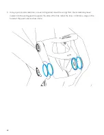
Страница 53: ...the pivot clevis and the frame 11 Install the outer 1 5 X 18mm inner diameter o rings over the pivot caps as shown 12 The final step is to re install the rear shock as directed in the shock removal replacement section starting on page 20 of this manual ...

Страница 54: ...54 Mayhem 130 150 Frame Parts Reference ...

Страница 55: ...55 Mayhem 130 150 Frame Parts Reference ...

Страница 56: ...1 21 FS90165 2020 MAYHEM 130 SHOCK PIN F 1 22 FS80003 M6 X 11 TORX 1 23 FS80006 M5 X 13 TORX 7 24 FS80007 P CLIP 3 25 FS90083 BRAKE MOUNT 1 26 FS90161 LEAF SPRING SCREW 32 4 27 FS90112 LEAF SPRING SPOOLER MAYHEM 1 28 FS90160 LEAF SPRING SCREW 21 0 4 29 FS90158 2020 MAYHEM LEAF SPRING CAP F 1 30 FS90159 2020 MAYHEM LEAF SPRING CAP R 1 31 FS90150 2020 MAYHEM UPPER PIVOT CAP 2 32 FS90157 2020 MAYHEM ...

Отзывы: