background image

16

Adjusting the Chain Tension 

During normal operation of your spinning bike, it may become necessary to loosen or tighten 
the chain for your best performance.
Loosen the M10x1.25 Nuts (51) M8 Nut (68) on the sides of the flywheel. 
To tighten the chain, turn the M8x50 Bolt (67) in a clockwise rotation equally on both sides 
using the Allen Wrench provided. 
To tighten the chain, turn the M8 Nut (68) in a clockwise rotation equally on both sides using 
the Multi Hex Tool with Phillips Screwdriver provided. 
While adjusting the chain tension, work on both sides of the flywheel.    Adjust the angle of 
the flywheel so it is straight front to rear and evenly spaced within the frame side to side. 
Adjust the angle of the flywheel by adjusting the M8x50 Bolts (67) on both sides of the 
flywheel test by slowly rotating the pedals. 
Finally, tighten the M8 Nut (68) and the M10x1.25 Nuts (51) on both sides alternating from 
side to side.

MAINTENANCE 

Cleaning

The spinning bike can be cleaned with a soft cloth and mild detergent.    Do not use 
abrasives or solvents on plastic parts.    Please wipe your perspiration off the bike after each 
use.    Please inspect all assembly bolts and pedals on the machine for proper tightness 
every week.

Storage 

Store the spinning bike in a clean and dry environment away from children.     

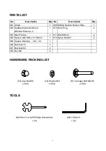
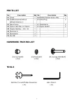
Allen Wrench 

Tool: 

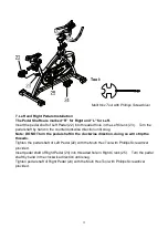
Multi Hex Tool with Phillips Screwdriver 

Содержание 206 9180

Страница 1: ......

Страница 2: ...UCTIONS 2 OPERATING THE COMPUTER 3 PARTS LIST 4 HARDWARE PACKING LIST 5 TOOLS 5 OVERVIEW DRAWING 6 ASSEMBLY INSTRUCTIONS 7 ADJUSTMENTS 14 MAINTENANCE 16 EMERGENCY STOP 17 MOVING THE SPINNING BIKE 17 W...

Страница 3: ...as adequate clearance This spinning bike is for home use only Only one person should be on the spinning bike while in use Wear comfortable and suitable clothing when using the spinning bike Do not use...

Страница 4: ......

Страница 5: ...5 1 070 Wire Plug 2 063 Main Frame 1 071 Bolt M5x30 2 064 Sensor with Wire L 1138mm 1 072 Nylon Nut M5 2 065 Square Bushing 38x 30 1 073 Bolt M5x15 2 066 Bolt M4x10 1 074 Washer 5 2 067 Bolt M8x50 2...

Страница 6: ...ll Chain Wheel 1 015 Round Knob 55x76xM16x1 5 2 045 Bearing 6000Z 2 016 Flywheel Protective Cover 1 046 Washer 10 4 017 Triangle Cover 1 047 Nut M10x1 0x5t 2 018 Saddle 1 048 Sleeve 14x 10 5x25 1 019...

Страница 7: ...5 1 070 Wire Plug 2 063 Main Frame 1 071 Bolt M5x30 2 064 Sensor with Wire L 1138mm 1 072 Nylon Nut M5 2 065 Square Bushing 38x 30 1 073 Bolt M5x15 2 066 Bolt M4x10 1 074 Washer 5 2 067 Bolt M8x50 2...

Страница 8: ...6 OVERVIEW DRAWING 4 5 6...

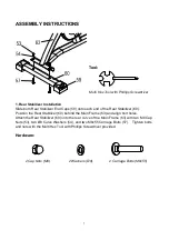
Страница 9: ...he Main Frame 63 and align bolt holes Attach the Rear Stabilizer 60 onto the rear curve of the Main Frame 63 with two M8 Cap Nuts 53 two 8 Curve Washers 54 and two M8x55 Carriage Bolts 57 Tighten bolt...

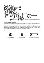
Страница 10: ...Main Frame 63 and align bolt holes Attach the Front Stabilizer 56 onto the front curve of the Main Frame 63 with two M8 Cap Nuts 53 two 8 Curve Washers 54 and two M8x55 Carriage Bolts 57 Tighten bolt...

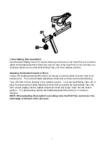
Страница 11: ...ockwise direction until it can be pulled out Pull out the Saddle Adjustment Knob 62 and then slide the Seat Sliding Tube 19 forth or back direction to the suitable position Lock the Seat Sliding Tube...

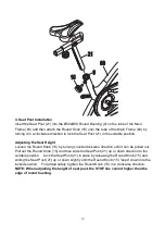
Страница 12: ...Knob 15 by turning counterclockwise direction until it can be pulled out Pull out the Round Knob 15 and then slide the Seat Post 21 up or down direction to the suitable position Lock the Seat Post 21...

Страница 13: ...e position Adjusting the Handlebar Height Loosen the Round Knob 15 by turning counterclockwise direction until it can be pulled out Pull out the Round Knob 15 and then slide the Handlebar Post 2 up or...

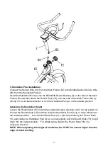
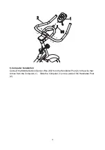
Страница 14: ...12 6 Computer Installation Connect the Middle Section Sensor Wire 69 from the Handlebar Post 2 to the wire that comes from the Computer 1 Slide the Computer 1 onto a plate of the Handlebar Post 2...

Страница 15: ...urn the pedal shaft in the clockwise direction doing so will strip the threads Tighten the pedal shaft of Left Pedal 22 with the Multi Hex Tool with Phillips Screwdriver provided Insert pedal shaft of...
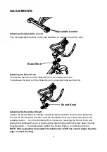
Страница 16: ...y turning counterclockwise direction until it can be pulled out Pull out the Round Knob and then slide the Handlebar Post up or down direction to the suitable position Lock the Handlebar Post in place...

Страница 17: ...the edge of round bushing Adjusting the Seat Forward or Back Loosen the Saddle Adjustment Knob by turning counterclockwise direction until it can be pulled out Pull out the Saddle Adjustment Knob and...

Страница 18: ...the angle of the flywheel so it is straight front to rear and evenly spaced within the frame side to side Adjust the angle of the flywheel by adjusting the M8x50 Bolts 67 on both sides of the flywhee...

Страница 19: ...BRAKE KNOB Continue holding the BRAKE KNOB down until the flywheel comes to a complete stop MOVING THE SPINNING BIKE Start by carefully pushing down on the handlebar until the rear end of the bike li...

Страница 20: ...of your entire exercise routine The WARM UP is an important part of any workout It should begin every session to prepare your body for more strenuous exercise by heating up and stretching your muscles...

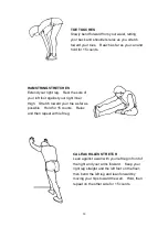
Страница 21: ...DRICEPS STRETCH With one hand against a wall for balance reach behind you and pull your right foot up Bring your heel as close to your buttocks as possible Hold for 15 counts and repeat with left foot...

Страница 22: ...an against a wall with your left leg in front of the right and your arms forward Keep your right leg straight and the left foot on the floor then bend the left leg and lean forward by moving your hips...

Отзывы: