background image

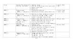
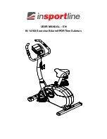
2-1.Troubleshooting -G575R


Faulty item  

Description 

Inspect and test procedures 

Suggesting replacement parts 

No power 

Display is not lit up while 
pedaling the bike  

1.Check all wire connections 
2. Check product fuse 
3.Check power board 
4.Replace MI drive board 

1.


Product fuse 

2.


Power board 

3.


MI drive board 

No RPM 

RPM display 0 while 
pedaling the bike  

1.


Check the wire connection 

2.


Power on again to test. If display or MI drive 
board problem will also cause RPM=0  

3.


Check to see if generator is turning 

4.


Replace MI drive board 

1.


MI drive board 

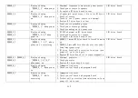
No resistance 

1.No resistance while 
pedaling 

1. Check to see if there is RPM signal on display 

while pedaling the bike 

2. Power on again to test. If display or MI drive 
board problem will also cause no resistance.  
3.Check drive belt or drive pulley 
4.Replace MI drive board 

1.Generator 
2.MI drive board 

No/bad 
telemetry heart 
rate reception 

Wearing strap, however 
no/bad heart rate signal  

1.


Check the Polar board wiring or replace it 

2.


Check interference sources, such as light or 
speaker 

1.


Polar board 

2. polar transmission 

No/bad contact 
heart rate 
reception 

No/bad HTR heart rate 
signal  

1. Make sure palms are holding on the sensors.   
2.Check the HTR board signal status 
3.Check HTR wiring problem 

1.


HTR board 

2.


HTR sensor 

3.


HTR wiring 

Key not 
function 
properly 

Key is not responding or 
stuck 

1.


Check the location of the problem keys 

2.


Numeric key pad problem, check or replace the 
membrane keys 

3.


If it is other key area, check or replace control 
board. 

4.


Replace key switches 

1.


Soft key pad 

2.


Control board or control board 
key board switch 


2-1-1 

Содержание G575R

Страница 1: ...G575R Repair manual Electronics ...

Страница 2: ...1 1 Product G575R 1 1 1 ...

Страница 3: ...1 2 Display G575R U 1 2 1 ...

Страница 4: ...1 3 Component placement G575R Display 1 3 1 Control board Program board Wireless HR board USB board ...

Страница 5: ...1 3 Component placement G575R frame 1 3 2 Power board MI drive board Flywheel Generator ...

Страница 6: ...1 3 Component placement G575R frame 1 3 3 MI drive board Power board Generator ...

Страница 7: ...1 4 Black diagram G575R 1 4 1 Display Board MI Drive Board Fuse SW Alternator keypad USB Board HR board C SAFE Board Power board Fan Sensor R Sensor L HTR bridge board HTR board ...

Страница 8: ...1 5 Wiring diagram G575R 1 5 1 ...

Страница 9: ...1 5 Wire connections G575R Display 1 5 2 Control board Program board To key pads To USB board To POLAR board To fan To HTR board To USB board CSAFE board To drive board To USB board ...

Страница 10: ...1 5 Wire connections G575R Display 1 5 3 CON3 CON4 7 CON5 CON6 CON1 CON2 CON3 CON1 CON2 USB board To control board To program board Bluetooth key To control board ...

Страница 11: ...1 5 Wire connections G575R MI Drive board 1 5 4 To generator To power board To display ...

Страница 12: ...1 5 Wire connections G575R Power board 1 5 5 Power board From drive board To control board Drive board to control board wire HTR to control board wire Generator wire connectiors ...

Страница 13: ...1 6 LED indicator G575R Display 1 6 1 LED16 POWER indicator LED18 COMM communication indicator ...

Страница 14: ...1 6 LED indicator G575R U MI Drive board 1 6 2 LED 3 COMM Communication indicator Program ...

Страница 15: ...e board to detect generator Main display Dot matrix Data displays CARDIO ADVISOR Weight loss zone Heart CARDIO zone CALORIES LEVEL TIME DISTANCE RPM METS SPEED HUMAN WATTS WATTS TO THE GRID Programs MANUAL INTERVAL PLATEAU RANDOM FAT BURN FIT TEST CUSTOM HR WT LOSS CARDIO Heart rate measurement Wireless Polar T34 HTR sensors Languages German French Spanish English US English International Japanese...

Страница 16: ...splay or MI drive board problem will also cause no resistance 3 Check drive belt or drive pulley 4 Replace MI drive board 1 Generator 2 MI drive board No bad telemetry heart rate reception Wearing strap however no bad heart rate signal 1 Check the Polar board wiring or replace it 2 Check interference sources such as light or speaker 1 Polar board 2 polar transmission No bad contact heart rate rece...

Страница 17: ..._2_2 Display showing ERROR_2_1 ERROR_2_2 when power on or exercising 1 ERROR_2_1 means IGBT on MI driver over current ERROR_2_1 means IGBT on MI driver too hot 2 Stop for hour before use it again 3 Replace MR drive board if it occurs frequently 1 MI drive board ERROR_3_1 Display showing ERROR_3_1 when power on 1 Islanding effect 2 Check product power cord installation 3 MI drive board protective f...

Страница 18: ...es 3 Or replace MI drive board to test 1 MI drive board ERROR_5_1 ERROR_5_2 Display showing ERROR_5_1 5_2 when power on or exercising 1 ERROR_5_1means MI drive board is forced to warm up 2 ERROR_5_2 means MI drive board is forced to shut down emergency stop 3 MI drive board self protective function turn power off on to try again 4 Replace MI drive board if it occurs frequently 1 MI drive board ERR...

Страница 19: ...ergy generated software version display Press CHANGE DISPLAY for 3 seconds to enter kph mph setting and total distance total time and control board software version display Model no and voltage setting Press hold Workout level change display keys for 3 seconds 2 1 4 ...

Страница 20: ...nections 2 Bad power board 3 Bad MI drive board 4 Bad control board Troubleshooting 1 Check product fuse 2 Check all wire connections 3 Check MI drive board LED indicator or replace drive board 4 Check power LED indicator on the control board or replace it 3 1 1 MI Drive Board Display board Power board AC1 AC2 Fuse SW POWER1 Fuse Switch Fuse Power board ...

Страница 21: ...ontrol board or drive board shut down 2 Bad wiring on generator 3 Bad MI drive board Troubleshooting 1 Turn power off on to test 2 Check generator A Check wire connections B Generator drive belt 3 Pedal once per second the RPM reading should be 60 4 Replace MI drive board to test 3 2 1 MI Drive Board Display board Alternator Key pads ...

Страница 22: ... control circuit controlling generator 2 Generator drive belt tension issue or bad generator 3 Bad MI drive board Troubleshooting 1 Check generator A Check wiring B Check drive pulley and belt 2 Replace MI drive board 3 Check generator performance 3 3 1 MI Drive Board Display board Alternator Energy reference Workout level RPM Watt 10 60 59W 20 60 136W 30 60 201W 40 60 220W 發電機 ...

Страница 23: ... reception Possible causes 1 Telemetry transmitter battery too low 2 Bad HR receiver board 3 Interference issue such as lights speakers Troubleshooting 1 Replace the transmitter battery 2 Check HR receiver board wiring 3 Replace the receiver board 3 4 1 Polar board Display board Transmitter Wireless HR board Polar T34 ...

Страница 24: ...idge board and LED indicator 4 Check HTR contact plates and wire connections 3 4 2 Display board HTR board Sensor R Sensor L Cable bridge HTR sensors HTR board HTR board LED indicator Indicator Name Description LED1 Telemetry Flashes to indicate incoming telemetry signal LED2 HTR contact Lights to indicate hands on the contact plates LED3 HTR output Flashes to indicate incoming HTR signal LED4 Hea...

Страница 25: ...ing Model G575R Malfunction item bad keys soft key pads Circumstances No response when pressing keys Possible causes 1 Bad membrane key pads Troubleshooting 1 Replace membrane key pads 3 5 1 Display board Soft key ...

Страница 26: ... Circumstance No response while pressing the display keys Possible causes 1 Bad display tact switches 2 Bad switch sleeve placement Troubleshooting 1 Check switch sleeves 2 Replace display tact switches 3 5 2 Tact switch Switch sleeves Tact switch Tact switches ...

Страница 27: ...ot responding Possible causes 1 Bad control board 2 Bad fan wire connections or bad fan motor Troubleshooting 1 Check the fan key and wire connections 2 Measure control board fan voltage 3 Replace control board or fan motor 3 6 1 Display board Fan motor Fan voltage V Fan low 3 v Fan mid 6v Fan high 9v Electro ma gnet ...

Страница 28: ...ssible causes 1 Bad MI drive board 2 Bad Control board to MI drive board Troubleshooting 1 ERROR_1_1 means power on error 2 Check wiring from control board to MI drive board 3 Check DSP MI driver on the MI drive board 4 Replace MI drive board 3 7 1 MI Drive Board Display board AC1 AC2 Fuse SW POWER1 MI drive board ...

Страница 29: ...oubleshooting 1 Press hold workout level change display for 3 seconds to enter voltage setting 2 Set the voltage on MI drive board for 110V or 220V for those products produced before May 2014 3 This problem only occurs on first installation or repair MI drive board 3 7 1 MI drive board 220V 110V Press hold workout level display change to set model no and AC VOLTAGE ...

Страница 30: ... control board to MI drive board Troubleshooting 1 ERROR_2_1 means MI driver IGBT over current ERROR_2_2 means MI driver IGBRT too hot 2 Above are the MI driver self protective functions Stop for hour before use it again 3 If message occurs frequently then replace the MI drive board 3 8 1 MI Drive Board Display board AC1 AC2 Fuse SW Alternator POWER1 MI drive board ...

Страница 31: ... 3 Bad MI driver Troubleshooting 1 ERROR_3_1 means Islanding 2 Check power cord 3 Make sure there is 5 seconds in between power off on 4 ERROR_3_1 message occurring once in a while is a self protective Function Turn power off and on to use it again 5 If message occurs frequently then replace the MI drive board 3 9 1 MI Drive Board Display board AC1 AC2 Fuse SW Alternator POWER1 MI drive board ...

Страница 32: ...ubleshooting 1 Proper voltage range 110V 105 132 Vac 220V 184 264 Vac 2 Check power source voltage range 3 This message is a self protective function when voltage is over the limit Stop using the product until the voltage regulates 4 If the voltage is within the range then replace the MI drive board 3 9 2 MI Drive Board Display board AC1 AC2 Fuse SW POWER1 MI drive board ...

Страница 33: ...n power on Possible causes 1 Abnormal power source frequency 2 Bad MI drive board Troubleshooting 1 This message is a self protective function Usually it will Not occur 2 Check power source frequency 3 Replace drive board to test 3 9 3 MI Drive Board Display board AC1 AC2 Fuse SW POWER1 MI drive board ...

Страница 34: ...4 when power on or exercising Possible causes 1 Power source interference or irregular 2 Bad MI drive board Troubleshooting 1 ERROR_3_4_ means the AC voltage mid point error 2 Check power source regularity 3 Replace MI drive board to test 3 9 4 MI Drive Board Display board AC1 AC2 Fuse SW POWER1 ...

Страница 35: ...n or exercising Possible causes 1 Power cord grounding issue 2 Improper power source grounding Troubleshooting 1 ERROR_3_5 means AC power grounding failing 2 Check power cord installation 3 Check power system for proper grounding 3 9 5 Product Power system Power plug Grounding system Grounding Grounding POWER1 ...

Страница 36: ...ossible causes 1 Power source interference 2 Bad MI drive board Troubleshooting 1 ERROR_4_3 means DC BUS voltage too high ERROR_4_4 means DC BUS error 2 Turn power off on to test 3 Check power source voltage irregularity 4 If it occurs frequently then replace MI drive board to test 3 10 1 MI Drive Board Display board AC1 AC2 Fuse SW POWER1 ...

Страница 37: ...oard self protective function 2 Bad MI drive board Troubleshooting 1 ERROR_5_1 means MI drive board is forced to warm up ERROR_5_2 means MI drive board is forced to shut down Emergency stop 2 MI drive board self protection Turn power off on to test 3 If it occurs frequently then replace MI drive board to test 3 11 1 MI Drive Board Display board AC1 AC2 Fuse SW POWER1 ...

Страница 38: ...Bad MI drive board Troubleshooting 1 ERROR_6_1 means generator over current ERROR_6_2 means generator voltage error ERROR_6_3 means generator too hot reserved for this function 2 Chech generator wire connections drive pulley and drive belt 3 Replace generator 4 Replace MI drive board 3 12 1 MI Drive Board Display board AC1 AC2 Fuse SW Alternator POWER1 MI drive board ...

Страница 39: ...wer on Possible causes 1 Bad MI drive board 2 Bad control board Troubleshooting 1 Check control board MI drive board wire connections 2 Check control board MI drive board IC program board installation 3 Replace control board MI drive board to test 3 13 1 MI Drive Board Display board POWER1 MI drive board ...

Страница 40: ...Possible causes 1 Communication interference 2 Programm not installed correctly Troubleshooting 1 Check wiring Between control board MI drive board 2 Product self protective function Turn power off on to test 3 Replace control board and MI drive board to test 3 13 MI Drive Board Display board POWER1 MI drive board ...

Страница 41: ... Pedal bike while in sleep mode to turn on power 3 Product quantity per pod New Green system products can be plugged into the same circuit breaker The allowed product quantity will be depending on the circuit specification as below Follow the circuit specification and do not over loading the circuit with too many products 3 14 1 Power grid Circuit breaker current GREEN SYSTEM quantity allowed 230V...

Страница 42: ...ersion 4252 2 Setting procedures A Model no setting Press hold WORKOUT LEVEL CHANGE DISPLAY keys until the display shows MODEL NO G875 or G575R or G575U Press WORKOUT LEVEL key to select model no and ENTER key to confirm B Voltage setting Press the above three keys until the display shows AC VOLTAGE 110V or AC VOLTAGE 220V Press WORKOUT LEVEL key to select 110V or 220V then press ENTER key to conf...

Страница 43: ...Other item Model no G575R Item MI Drive board voltage setting Description 1 MI drive board version is before 4252 Before May 2014 2 Set power source voltage 3 16 1 110V 105V 132V Short Cap 220V ...

Страница 44: ...er source voltage error ERROR_3_3 AC power source frequency error ERROR_3_4 AC mid point error reference error ERROR_3_5 AC grounding failed ground fault ERROR_4_3 DC_BUS voltage too high ERROR_4_4 DC_BUS error ERROR_5_1 Forced to warm up ERROR_5_2 Forced to shut down EngStop ERROR_6_1 Generator over current ERROR_6_2 Generator voltage error ERROR_6_3 Generator too hot ERROR_8_1 Micro Inverter com...

Страница 45: ... default value of 30 00 press INCLINE key to adjust the range of adjustment is 5 60 minutes Afterwards press ENTER to confirm C Language setting The display shows GERMAN XX MILE H H or XX KM H_H press WORKOUT LEVEL to change the setting Afterwards press ENTER to confirm D Total distance display The display shows DIST XXXXXXKM or DIST XXXXXXMILE for total distance display Press ENTER to exit E Tota...

Страница 46: ...key the display will show UNIT KPH MPH TIME LITMIT ZZZ TIME XXMIN until the display shows GERMAN or 0 MILE H_H for language setting 0 1 2 3 represents country language code see below Press WORKOUT LEVEL to select the desired language press ENTER to confirm 2 Country language code GERMAN O KM H_H FRENCH 1 KM H_H POLISH 2 KM H_H SPAINLISH 3 KM H_H JAPANESE 5 KM H_H US ENGLISH 6 MILE H_H UK ENGLISH 1...

Страница 47: ...Other item Model no G575R Item Electronic component specification Description 3 20 1 ...

Страница 48: ... inspection A Check generator wire connections B Check generator belt tension C Check generator pulley installation 2 Measure voltage A Pedal bike once per second RPM reading should be 60 B When RPM is 60 at LEVEL 20 the WATTS TO THE GRID window should show 136W 4 1 1 Generator RPM 60 LEVEL 20 WATTS to the Grid 136 ...

Страница 49: ...Testing item power source voltage inspection Method 1 Input voltage Blue brown wires AC 110V or 220V 2 Output voltage Black brown to yellow orange DC 12V 4 2 1 Output voltage black brown to yellow orange DC 12 V Input voltage black brown AC 110 or 220V ...

Страница 50: ...t Method 1 There is RPM detecting circuit inside MI drive board It will detect the AC voltage and figure out the RPM value 2 Pedal once per second the RPM reading should be about 60 3 If the reading is off a lot check generator pulley belt or replace MI drive board 4 3 1 ...

Страница 51: ...MI drive board communication Method 1 Turn on the power and visually inspect the LED3 indicator flashing status Normally it is flashing regularly If irregular flashing occurs it means there is a communication error check wiring connections at this time 4 4 1 ...

Страница 52: ...m Power generated measurement Method 1 There is a circuit inside the MI drive board which will calculate the voltage generated Pedaling level setting the WATTS TO GRID window display as below 4 5 1 LEVEL RPM WATTS 10 60 59W 20 60 136W 30 60 201W 40 60 220W ...

Отзывы: