


Page
/ Bulletin 30-21
OPERATION
“B” TYPE
NORMAL (OUTDOOR) CONDENSER - De-energized
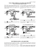
See Figure 1. With the pilot valve de-energized, high side pressure
is prevented from entering the cavity above the piston assembly.
At the same time, the upper pilot port is open to suction pressure.
The resulting pressure differential across the piston moves the
piston-seat assembly to close the reclaim condenser port (upper
main port). In this mode, the refrigerant flows to the normal con-
denser. The pilot valve opens the cavity above the piston to suc-
tion. This allows the reclaim condenser to be pumped out through
a small bleed hole in the piston. The pump out process reduces the
reclaim condenser to suction pressure. Once suction pressure is
reached, the flow through the bleed hole in the piston stops. There
is no high to low side bleed with continued operation in the nor-
mal condenser mode. For a more efficient pump out of the reclaim
condenser, a normally open solenoid valve can be added to the
lowest physical location of the reclaim coil to remove liquid.
“C” TYPE
NORMAL (OUTDOOR) CONDENSER - De-energized
With the pilot valve de-energized, high side pressure is prevented
from entering cavity above the piston-seat assembly. At the same
time the upper pilot port is opened to suction pressure. The result-
ing pressure differential across the piston moves the piston-seat
assembly to close the reclaim (upper) main port, thereby eliminat-
ing high to low side bleed and the resulting capacity loss with the
system in the normal condenser mode.
“B” AND “C” TYPE
RECLAIM (REHEAT) CONDENSER - Energized
When the pilot valve is energized, high side pressure is permitted
to flow through the lower pilot port at the same time the upper
pilot port is closed to suction. High side pressure build up on top
of the piston moves the piston-seat assembly to close the normal
condenser port and open the reclaim (upper) main port. With the
upper pilot port closed, there is no high to low side bleed and
resulting capacity loss with the system in the reclaim mode.
Valves using the MKC-1 coil may be used on fluids or gases where
the temperature does not exceed 240°F, while the valve ambient is
120°F. The coil is Underwriters Laboratory Class F rated.
TYPES B5D, 8D, 12D & 16D 3-WAY HEAT RECLAIM VALVES
Bulletin 30-21, April 2007 supersedes Bulletin 30-21, June 2001 and all prior publications. © 2007 by Sporlan Division, Parker Hannifin Corporation
Type
Port
Size
Connection
ODF Solder
Inches
A
B
C
D
E
F
G
H
J
B5D5B
B5D5C
5/8
5/8
5.00 4.36 3.22 3.22 0.79 3.84 0.50 2.94
1.64
8D7B
8D7C
3/4
7/8
5.18
5.06
3.44 3.44 1.13 2.63
0.75
2.89
8D9B
8D9C
1-1/8
5.13
0.91
12D11B
12D11C
1-1/4
1-3/8
6.87 6.94 4.19 4.19 2.38 4.25
0.97
12D13B
12D13C
1-5/8
1.09
12D17B
2-1/8
1.25
16D17B
16D17C
2
2-1/8
8.18 9.53 5.47 5.47 3.50 5.44 1.25 3.17
NOT FOR USE WITH HAZARDOUS OR CORROSIVE FLUIDS
INSTALLATION
PIPING SUGGESTIONS
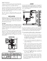
Valves must be installed in a horizontal or vertical position with
the coil level with or above the valve body. Install Heat Reclaim
Valves so the connections are in the proper flow direction as
shown in Figure 2.
Figure 3, page 4, shows piping schematics only to illustrate the
general installation of the Heat Reclaim Valves. Sporlan recom-
mends that recognized piping references be consulted for assis-
tance in piping procedures. Sporlan is not responsible for system
design, any damage resulting from system design, or for misap-
plication of its products.
Proper support of heat reclaim valves is essential. Concentrated
stresses resulting from thermal expansion or compressor vibra-
tions can cause fatigue failure of tubing, elbows and valve fittings.
Fatigue failures can also result from vapor propelled liquid slug-
ging, and condensation induced shock. The use of piping brackets
close to each of the three way valve fittings is recommended.
Suction
Reclaim
Condenser
Compressor
Discharge
Normal
Condenser
1/4” SAE
A
B
D
C
E
G
Optional 1/2”
Conduit Boss
J
F
Figure 2
H
Compressor
Discharge
Suction
Reclaim
Condenser
Bleed Hole
Figure 1
“B” TYPE
RECLAIM CONDENSER
PUMP OUT
DIMENSIONS – Inches


