IP Network Intercom Terminal Installation Instructions
1
①
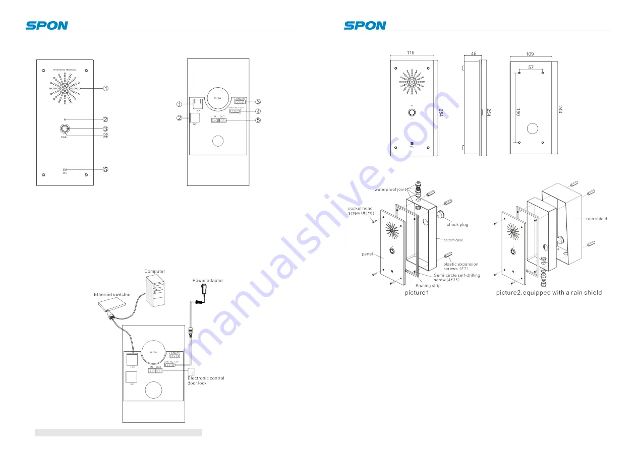
Speaker: Restore the remote live voice.
②
Status Indicator
③
Button: Press this button to call the server
designated terminal.
④
Button Indicator
⑤
Pickup microphone: Pick up the live voice.
①
Network input port
②
Control panel interface
For debugging and temporary
terminal configuration use.
③
Audio output
④
Power input :Access the 12V DC
power
⑤
Alarm input /alarm output port
Interface Instruction
Front
Back
Appearance Installation Diagram
Note
:
For more details please refer to user manual.
IP Network Intercom Terminal Installation Instructions
2
Connection Diagram (Unit: mm)
Schematic Diagram of Installation
Installation Steps
①
Put sealing strip on the bottom case correspondingly(Note: Sealing strip joints left a
5 mm gap);
②
Connect to waterproof joint, put chock plug to hole outlet, let the power cord go
through the chock plug and the cable go through the waterproof joint, then straighten all
these lines.
③
Using plastic expansion screws to fix bottom case on wall
④
Using the socket head screw to fix panel on bottom case.
Note
: 1
、
According to the real situation of the project to choose the bottom shell wiring
methods installed by upwards or downwards.
2
、
If it`s equipped with a rain shield, please put bottom case into the rain shield, as
picture2 shows.
IP Network Terminal Setting
(
1
)
Using couplet cable to connect computer and terminal. In [CD: \ tools \] directory, find
and run "IP configuration tool" audio terminal, start it, enter the default password


