background image

11

Track  One

Preamplifier

Control Elements

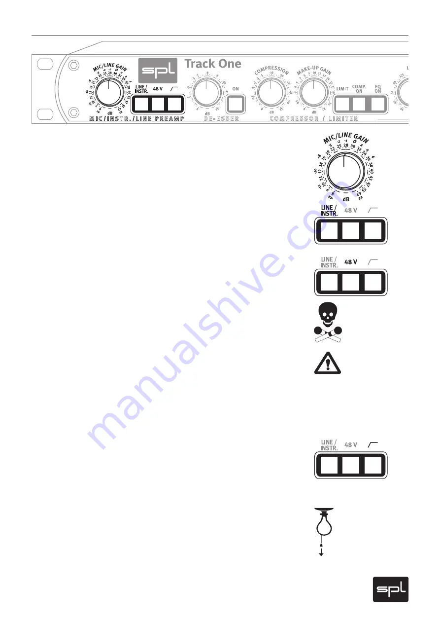
MIC/LINE GAIN, LINE/INSTR.

The MIC/LINE GAIN control determines the level of preamplification for microphone and line 
or instrument signals. In standard mode you control microphone preamplification. Engage 
the LINE/INSTR. switch to control line or instrument signals. 

The preamplification values for microphone signals cover a range from +8 dB up to + 63 dB. If 
the optional microphone input transformer is installed, the scaled values are to be increased 
by ca. +14 dB (also see page 22, “Information on I/O transformers”). 

The  preamplification  values  for  line  and  instrument  signals  cover  a  range  from  -12 dB  to 
+22 dB.

48 V

The 48  V switch activates phantom power for condenser microphones with built-in amplifiers. 
Phantom power should only be activated when using microphones that require it.  

VERY IMPORTANT: All microphones with balanced, ground-free outputs, can be used with 
the phantom power activated. Please be sure to deactivate phantom power with all other 
microphones. Unbalanced microphones may only be used with phantom power deactivated.


Activating phantom power

Please always follow these instructions to active and deactivate phantom power – also when 
changing microphones. The input stage of the Track  One can be damaged if you ignore these 
procedures!

1.  Connect the microphone to the Track  One. 
2.  Now activate phantom power to use the microphone.
3.  After recording first deactivate phantom power. 
4. 

Wait at least one minute after deactivation of phantom power before disconnecting the 
microphone! 

This ensures residual current will be discharged. 

High pass

This switch activates the high-pass filter (often also called a “rumble filter”), which operates 
from a low 50 Hz downwards with a high slope of 12 dB/octave. Therefore, amplification of 
unwanted low frequencies is avoided effectively while influences on vocal frequencies are 
not to be expected.

Gain adjustments

For perfect levelling of the preamplifier firstly switch off all other modules and set the OUTPUT 
control to 0 dB. The signal can now be levelled with the assistance of the PPM OUTPUT display. 
To achieve a good signal level the values should range between 0 and +3 dB. At these levels 
an optimal drive level and enough headroom for further processing (e. g. adding level in the 
EQ stage) is ensured. The Clip LED will warn you of potential peaks; if during recording the 
CLIP LED illuminates, the gain value is to be reduced accordingly.

Содержание Track One 2960

Страница 1: ...Manual Channel Strip Track One Model 2960...

Страница 2: ...0 Fax 49 0 2163 983 420 E Mail info spl info Internet www spl info The construction of the Track One Model 2960 is in compliance with the stan dards and regulations of the European Community Notes on...

Страница 3: ...ts 11 De Esser EQ ON De Esser control SPL De Esser technology 12 Compressor Limiter COMP ON LIMIT COMPRESSION 13 MAKE UP GAIN SPL compressor technology 14 Equalizer ON LMF LMF MHF 15 MHF Recommendatio...

Страница 4: ...ple near a wash basin or bath in a damp cellar near swimming pools or the like In such cases there is an extremely high risk of fatal electrical shocks Insertion of foreign objects or fluids Never all...

Страница 5: ...Be sure that any service technician uses original replacement parts or those with identical specifications as the originals Incorrectly substituted parts can lead to fire electrical shock or other da...

Страница 6: ...ly in live situations Due to its excellent sound quality the Track One is a highly recommended alternative to built in console pre amps and processing tools All the modules are immediately at hand for...

Страница 7: ...right sleeve ground Pin wiring XLR input sockets 1 ground 2 hot 3 cold Pin wiring XLR output sockets 1 ground 2 hot 3 cold PUSH 2 1 3 2 1 3 Pin wiring 1 4 TS socket mono jack tip left sleeve ground Ma...

Страница 8: ...tentials between driver and receiver would produce disturbances In balanced connections a reference signal with reversed polarity is transmitted additionally to the audio signal through a second wire...

Страница 9: ...shielding of the housing MIC IN You can connect any kind of microphone to the MIC IN socket dynamic condenser tube and ribbon microphones 48 volts phantom power which is required for some microphones...

Страница 10: ...P LINK compressor link feature allows to operate two Track One compressors with one control signal to ensure coherent stereo results The MASTER SLAVE switch determines which unit operates as master an...

Страница 11: ...ollow these instructions to active and deactivate phantom power also when changing microphones The input stage of the Track One can be damaged if you ignore these procedures 1 Connect the microphone t...

Страница 12: ...This method of operation has distinct advantages because it is unobtrusive and helps retain the original tonal quality Compressor typical side effects such as lisping or nasal tones do not occur Final...

Страница 13: ...s processing earlier than with hard knee curve see page 20 diagram 1 curve B Hard knee compressors can sometimes gain more loudness but they process abruptly and the danger to ruin a recording with co...

Страница 14: ...tomatic setting of the release times is dependent on the input signal too Fast and large level fluctuations are correspondingly processed with shorter time constants than minor fluctuations in order t...

Страница 15: ...sically more sensible processing of the frequency spectrum than with constant Q filters if a more thorough setting has been chosen this will lead to far preciser definition of the frequency range to b...

Страница 16: ...d with MHF AIR BAND The high frequency filter in the equalizer module is described as the AIR BAND A coil capacitor filter with so called bell characteristics and a center frequency of 17 5 kHz comes...

Страница 17: ...overloads occur during recording the quickest remedy is to gradu ally reduce the respective gain control in the preamplifier SIG The SIGNAL LED illuminates when a signal is being received at the prea...

Страница 18: ...Copy master recall settings Artist Album Gig Title Engineer Track s Groups Date...

Страница 19: ...crophone Input Frequency response 10Hz 200kHz 3dB Maximum input level 8dBu Common mode rejection at 20dBu 1kHz 80 dB 10kHz 68dB THD N Amplification A weighted 20dB 97 5dBu 40dB 91 0dBu 65dB 69 6dBu Dy...

Страница 20: ...LMF A C B Diagram 1 compressor curves Line A displays the ratio between input and output Line B shows the curve character istics of the compressor Line C protrays the limiter s curve characteristics...

Страница 21: ...21 Track One MHF Air Band Measurements Diagram 4 various cut and boost settings of the Air Band filter Diagram 3 various cut and boost settings of the MHF filter at around 1 8kHz...

Страница 22: ...ynchronization The yellow Sync Lock LED illuminates when a valid sync signal is present at the SYNC INPUT and the converter is automatically synchronized to the external sample rate To prevent interfe...

Отзывы: