
S
S
e
e
r
r
v
v
i
i
c
c
e
e
M
M
a
a
n
n
u
u
a
a
l
l
D
D
i
i
a
a
g
g
r
r
a
a
m
m
s
s
a
a
n
n
d
d
S
S
c
c
h
h
e
e
m
m
a
a
t
t
i
i
c
c
s
s
D
D
i
i
a
a
g
g
r
r
a
a
m
m
s
s
a
a
n
n
d
d
S
S
c
c
h
h
e
e
m
m
a
a
t
t
i
i
c
c
s
s
2
2
3
3
150mm White Wire
12PIN 800mm Upper Connection
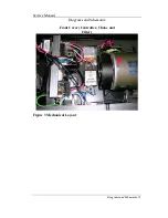
ALT-6330A
M-
CONSOLE
100mm Black Wire
BREAKER
AC Switch
Red Wire
Motor
Black Wire
Controller
Green Wire
JK1
10
0m
m
B
la
ck
W
ire
Core
12PIN 1150mm Bottom Connection
Sensor Wire 1000mm
G
re
en
W
ire
10
0m
m
G
re
en
W
ire
(G
re
en
w
ith
ye
llo
w
)
C
O
N
N
EC
TO
R
CONNECTOR
PLUG
A
C
2
(1
20
V~
)
Incline Motor
JK2
Incline VR
White Wire
Black Wire
Red Wire
JK3(Incline-VR)
DOWN (120V~)
COM (NEUTRAL)
UP (120V~)
M+ (0 ~ 110V-)
AC
1
(1
20
V
~)
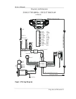
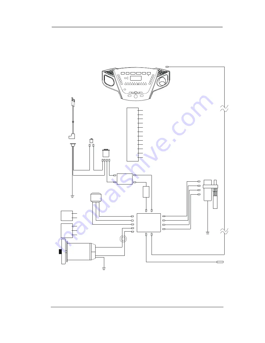
Z100CE TREADMILL CIRCUIT DIAGRAM
1
2
3
4
5
6
7
8
9
10
11
12
JK1
Red
Purple
Gray
Green
Blue
Orange
Yellow
Brown
Black
Light blue
Pink
White
UP
SPD
VR2
VR3
SPD
VR1
SLOW
GNP
VCC
FAST
DOWN
S/W
1
2
3
JK3
VR2
VR3
VR1
A
B
2
1
JK2
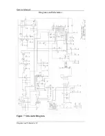
12
PI
N
13
00
mm
Mi
dd
le
Co
nn
ec
ti
on
4PIN 300mm Black Wire
3PIN 200mm Red Wire
2PIN 200mm Blue Wire
Adaptor
Li
ne
Lo
ad
C
ho
ke
Filter
150mm White wire
10
0m
m
w
hi
te
w
ire
100mm Black wire
100mm
10
0m
m
Rang core
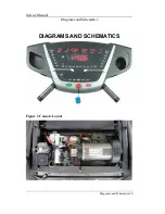
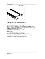
Figure 6 Wiring Diagram


