


Please contact customer service at:
Spireon.com/skylink
Phone:
877-600-6101
©2018 Spireon, Inc. All rights reserved.
Installation Guide (Standard)
Talon
™
GPS Device
Installation Options:
Depending on each of the optional accessories you’ve chosen, if any, the Talon can be installed in one of three
ways:
1.
The standard installation simply cuts o
ff
the quick disconnect on the device harness and hard-wires it to the vehicle.
2.
The optional pre-install harness can also be hard-wired using the same steps to make use of the quick disconnect
on the device harness.
3.
The third option uses an OBDii pass through cable that plugs into the vehicle’s OBDii port and also features a quick
disconnect which connects to the one on the device harness. (Not compatible w/ optional warning buzzer).
Standard Installation Instructions:
1.
Splice the supplied in-line fuse into the red wire in the device
harness. (Failure to install fuse may result in vehicle and / or device
damage).
2.
Using a digital voltmeter, locate a constant 12V source (meter should
read 12V with the vehicle’s ignition in the o
ff
position) and a solid
chassis ground location.
3.
Find a mounting location for the Talon that is clear of metallic
obstructions from above that could cause interference with GPS
signal reception. Be sure that the Talon is mounted in a manner that
positions the printed ‘This Side Down’ indicator toward the floor of
the vehicle.
4.
For installations without the pre-install harness or OBDII pass
through cable, cut o
ff
the quick disconnect on the device harness
and connect the red wire to your constant 12V source and the black
wire to ground.
5.
The vehicle must have a voltage
≥
13V to be in full operational mode.
If the source is
≤
13V you must start the car and have it running during
validation of the install.
6.
On initial power up, the LED indicators should show a flashing green
LED and a flashing red LED while scanning for cellular and GPS
signals, respectively. When the green and red LEDs stop flashing and
remain solid, adequate cellular and GPS signals have been acquired.
Important:
It may take five to seven seconds
to see any LED activity
and up to
15 minutes to get
an initial GPS lock.
Caution:
If, after 15 minutes, you are
still unable to get GPS and / or
cellular signals, reposition
and try again.
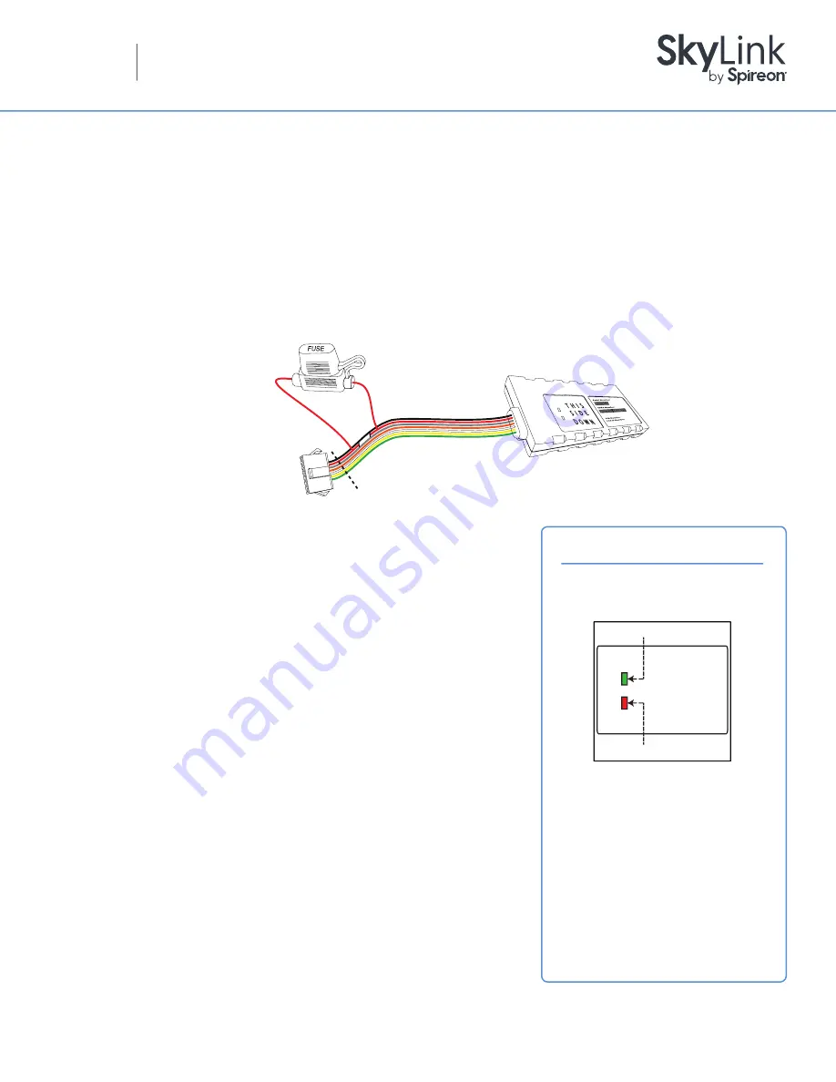
LED Troubleshooting
Flashing = Scanning for Signal
Solid = Signal Acquired
T H I S
S I D E
DOWN
Green = Cellular Signal
Red = GPS Signal
Wire Diagram
Installation
(Standard):
Cut Here for Standard Installation
(Do Not Cut When Using
Preinstall or OBD2 Harness)


