Getting Started
Procedure 5: Perform Cable Connections
26
|
Getting Started with Spirent TestCenter
Procedure 5: Perform Cable Connections
This section explains how to connect cables to the connectors. We recommend that you
complete Procedures 5 through 11 in this guide before you connect to an application or
device under test (Procedure 12).
•
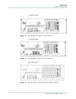
Panel connectors on the SPT-N4U are shown in
.
•
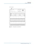
Panel connectors on the SPT-N11U and SPT-N12U are shown in
.
•
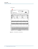
Panel connectors on the SPT-C50 are shown in
.
•
Panel Connectors on the SPT-C50-S2-RX are shown in
.
Notes: •
For complete installation and setup information for the Spirent C1 or the
PX3/DX3-QSFP-DD-8 appliances, refer to the installation documentation
that is included in your appliance shipment.
•
Refer to FAQ18073 for information about External Time Reference (ETR)
methods you can use to sync multiple remote chassis. Go to the Customer
Service Center (CSC) (
) and type
FAQ18073
in
the
Search
box. Press Enter.
Figure 1-2.
SPT-N4U Front Panel
Removable Hard
Drive Tray
LEDs for Chassis
Connection Status
External Time Reference Connectors
DVI-I Connector
USB Ports
Ethernet Admin
Port
Multiple Chassis
Connection Ports
Note
: The two (2) Power Cord
Connectors are on the back of the
chassis (not shown). Depending on the
model, there will be one (1) or two (2).
Содержание TestCenter
Страница 10: ...About this Guide How to Contact Us 10 Getting Started with Spirent TestCenter ...
Страница 86: ......


