IM-P054-08 CH Issue 2
MPC2 Spirax-Monnier
High Efficiency Compressed Air Filter / Regulator
Installation and Maintenance Instructions
IM-P054-08
CH Issue 2
0549750/2
Printed in the UK
© Copyright 2001
What is the MPC2 used for?
The MPC2 is used to provide very high
quality compressed air.
There are an ever increasing number of
applications where compressed air of a
particularly high quality is required. Typical
examples include air bearings on machine
tools, air gauging equipment, instrument air
supplies, fluidic systems, breathing air,
pneumatic positioners, etc.
How efficient is the MPC2?
Spirax-Monnier coalescing filters when
tested to BS 3928 or the D.O.P. test, are
more than 99.999% efficient.
In the sodium flame test (BS 3928) the element
is challenged by a cloud of salt particles of mass
mean diameter of 0.6 micron. In the American
D.O.P. test, a cloud of droplets of mass mean
diameter 0.3 micron is used.
How does the MPC2 work?
These units filter out solid contaminants
and remove oil and water liquids and
aerosols, by coalescing.
Contaminated air flows to the inside of the
filter cartridge. The cartridge contains a
labyrinth of micro fibres which will trap solid
particles down to sub micron size. Fine liquid
mist and aerosols on their journey through
the depth of the element, will strike one or
other of the fibres and will be retained on
them by inter-molecular forces.
As the droplets migrate through the element
due to the air flow, they will join (coalesce)
with others, growing in size. A specially
designed porous plastic sock forms the outer
layer of the filter cartridge. This encourages
further coalescing, so that the droplet mass is
sufficient to allow it to gravitate to the sump of
the filter from which they can be drained
manually. The porous plastic sock also
reduces the possibility of re-entrainment.
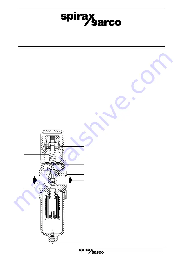
With the adjustment knob (1) rotated fully
anticlockwise, the valve return spring (13) will
keep the main valve (8) shut. Clockwise rotation
of the adjustment knob will compress the main
control spring (11), deflect the diaphragm
assembly downwards (10), opening the main
valve (8). As air flows to the downstream (9)
side of the filter/regulator, the secondary
pressure increases. The secondary pressure is
sensed on the underside of the diaphragm. As
the controlled pressure varies, so does the
force on the underside of the diaphragm. When
this force (proportional to the secondary
pressure) equals the compression in the main
control spring, the main valve will shut. Any fall
in secondary pressure will cause the main valve
to open sufficiently to meet the air flow
requirements and maintain the set secondary
pressure.
Any appreciable rise in the secondary pressure
from its set value will cause the diaphragm and
the push rod (12) to lift. This will allow air to
escape through the centre of the push rod to
atmosphere. When excess pressure has vented,
the orifice in the push rod will reseat on the main
valve.
Ensure that the bowl is regularly drained by
means of the quick action drain valve (16).
11
12
13
1
2
10
8
9
16
17
Tamper
proof cap


