Spirax Sarco FTC62 Скачать руководство пользователя страница 22

IM-P179-15 

CMGT Issue 3

22

start of text under grey section header box

start of text continuing from previous page

TRANSLATION RUN OVER

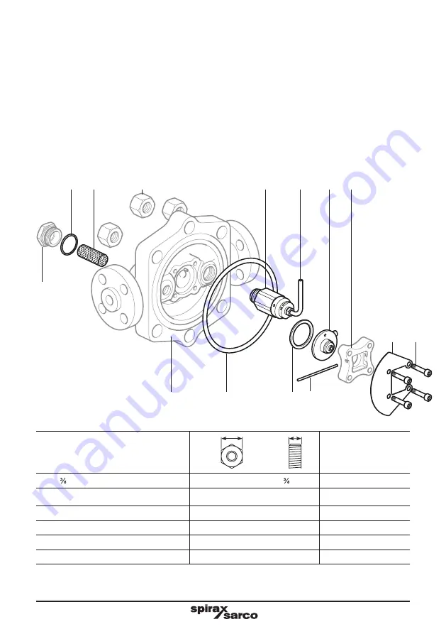
6.2.3 Replacing the Air vent assembly

Gain access to the internals by removal of the cover (

2

) by undoing the six ¾" UNF (

4

) nuts holding the 

cover in place.

Then remove the air vent assembly (

9

) and the air vent tube (

10

).

Put a little anti-seize on the thread of the new air vent assembly (

9

) together with the tube (

10

preassembled, tighten following the guidance of the torque setting in the table.

Note 1:

 The air vent tube must be aligned and pointing in the same direction as the directional arrow upon 

the seat clamp (

11

).

Note 2: 

when the internals have been assembled, with the pin (

13

) fully inserted so that it touches the air 

vent assembly it may appear long, do not cut it, it is purposely long to inhibit that with vibration its movement 

is limited, therefore, it is impossible for it to become free.

Parts drawn in a grey line are 

not supplied as spares.

Recommended tightening torques

Item Part

Inch

or 

mm

N m

lbf ft

3

" NPT Square head plug

11 mm A/F

" NPT

As required

4

¾" UNF Hex. Nut

1.125" A/F 

¾" UNF

252-260

186-192 

6

Strainer cap

32 mm A/F

M28 x 1.5

170-190

125-140

9

Air vent assembly

32 mm A/F

M22 x 1.5

80-88

59-65

10

Air vent tube assembly

11 mm A/F

M10 x 1.5

10-12

7-9

12

M6 x 30 Socket head cap screw

5 mm A/F (Hex Key)

M6

14-16

10-12

8

6

1

7

9

10

17

11

22

12

18

19 13

4

Содержание FTC62

Страница 1: ...formation 2 General product information 3 Installation 4 Commissioning 5 Operation 6 Spare parts and maintenance Copyright 2018 Printed in GB 1792050 3 FTC62 and FTS62 Ball Float Steam Traps Installat...

Страница 2: ...ered ii Check material suitability pressure and temperature and their maximum and minimum values If the maximum operating limits of the product are lower than those of the system in which it is being...

Страница 3: ...e any protective clothing to protect against the hazards of for example chemicals high low temperature radiation noise falling objects and dangers to eyes and face 1 11 Permits to work All work must b...

Страница 4: ...present a health safety or environmental risk This information must be provided in writing including Health and Safety data sheets relating to any substances identified as hazardous or potentially ha...

Страница 5: ...evention of water hammer Steam trapping on steam mains Steam Mains Do s and Don ts Steam Steam Flow Flow 30 50 metre intervals Gradient 1 100 Gradient 1 100 Trap set Trap set Trap set Condensate Conde...

Страница 6: ...e correct torque figures 1 1 4 2 3 8 2 6 3 7 Flange bolts should be gradually tightened across diameters to ensure even load and alignment Guides Guides Limit rods Limit rods Fixing point Medium dista...

Страница 7: ...rements of the Pressure Equipment Directive PED and carries the mark Certification These products are available with certification to EN 10204 3 1 Note All certification inspection requirements must b...

Страница 8: ...2 3 Pressure temperature limits ISO 6552 FTC62 Screwed see Section 2 4 page 9 Socket weld Flanged ASME Class 600 Flanged EN 1092 PN100 see Section 2 5 pages 10 FTS62 Screwed see Section 2 6 page 11 So...

Страница 9: ...e pressure 102 1 bar g 38 C 1480 psi g 100 F TMA Maximum allowable temperature 425 C 57 5 bar g 797 F 834 psi g Minimum allowable temperature 29 C 20 F PMO Maximum operating pressure for saturated ste...

Страница 10: ...ssure 100 bar g 50 C TMA Maximum allowable temperature 400 C 59 5 bar g Minimum allowable temperature 10 C PMO Maximum operating pressure for saturated steam service 70 8 bar g 287 C TMO Maximum opera...

Страница 11: ...wable pressure 99 3 bar g 38 C 1 440 psi g 100 F TMA Maximum allowable temperature 425 C 56 bar g 797 F 812 psi g Minimum allowable temperature 29 C 20 F PMO Maximum operating pressure for saturated s...

Страница 12: ...able temperature 425 C 58 9 bar g Minimum allowable temperature 29 C PMO Maximum operating pressure for saturated steam service 65 8 bar g 283 C TMO Maximum operating temperature 425 C 58 9 bar g Mini...

Страница 13: ...1092 1 and ASME 600 B 16 5 face to face dimensions Size Flanged Common sizes PN100 ASME 600 A B Weight A B Weight C D E F DN15 300 304 0 25 0 261 299 24 0 172 5 148 251 5 239 DN20 300 316 5 26 0 271...

Страница 14: ...A B Weight C D E F DN15 190 287 5 22 0 172 5 148 251 5 239 DN20 190 287 5 22 0 172 5 148 251 5 239 DN25 190 287 5 22 0 172 5 148 251 5 239 A F 2 9 Screwed and socket weld dimensions weights approximat...

Страница 15: ...metallic air vent will be open and provides additional capcaity to the main valve The following table gives the minimum additional cold water capacities from the air vent on all sizes Note The Air ven...

Страница 16: ...ation on steam or other high temperature applications 3 4 The trap must be fitted with the float arm in a horizontal plane so that it rises and falls vertically Note The trap can be visually checked f...

Страница 17: ...damage may occur to the float that would render the trap inoperative The ball float trap is a continuous discharge device removing condensate the instant it forms On start up the bimetallic air vent...

Страница 18: ...mbly 32 mm A F M22 x 1 5 80 88 59 65 10 Air vent tube assembly 11 mm A F M10 x 1 5 10 12 7 9 12 M6 x 30 Socket head cap screw 5 mm A F Hex Key M6 14 16 10 12 Note Before actioning any maintenance obse...

Страница 19: ...long cap screw x 4 12 Pivot pin 13 Float assembly 14 ball 15 Conical spring 16 Valve seat and discharge pipe assembly 17 S type gasket Spirally wound gaskets 8 18 and 19 Baffle plate 22 Overhaul kit...

Страница 20: ...n with the Float in situe in a line or securely fastened in a vice Parts drawn in a grey line are not supplied as spares Recommended tightening torques Item Part inch or mm N m lbf ft 3 NPT Square hea...

Страница 21: ...embly Gain access to the internals by removal of the cover 2 by undoing the six UNF 4 nuts holding the cover in place Withdraw the pin 13 remove the float assembly 14 stainless ball 15 and conical spr...

Страница 22: ...2 when the internals have been assembled with the pin 13 fully inserted so that it touches the air vent assembly it may appear long do not cut it it is purposely long to inhibit that with vibration it...

Страница 23: ...oving the strainer cap 6 Remove the strainer screen 7 and gasket 8 Fit a new or cleaned strainer screen into the recess in the cap 6 A new gasket 8 must always be fitted and the cap 6 screwed into the...

Страница 24: ...in the sequence in Figure 5 opposite each stage to be repeated at least twice to ensure even gasket compression M6 cap screws 12 to be tightened in three stages also firstly 60 and then 80 of finishe...

Страница 25: ...nd of the air vent tube sub assembly 10 must always be uppermost Regardless of flow direction the arrow on the seat clamp 11 must always be pointing upwards See notes for torque tightening procedure 1...

Страница 26: ...IM P179 15 CMGT Issue 3 26...

Отзывы: