


IM-P481-04
CTLS Issue 4
11
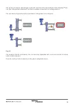
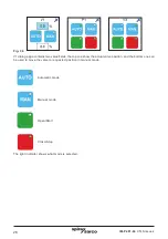
Terminal layout overview
Fig. 5
Terminal layout detailed
Note:
for detailed wiring schematic options please refer to the 'Operations manual'.
X1 - X5
PT100
inputs
X6 - X8
4 - 20 mA
inputs
X9 - X10A
4 - 20 mA
outputs
X10B - 10C
actuator
signals
X11
Bypass pump
X14 - X16
volt free
signals
X17
remote
enable
X12
Bypass valve
X13A-C
High limit
valve
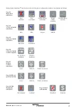
1.
Basic
2.
Independent high limit
3.
Independent high limit with safety
4.
American standard
X1
-
Water temperature IN
X2
-
Water temperature OUT
X3
-
Steam temperature
X4
-
Condensate temperature
X5
-
High limit temperature
Group X6 to X10A
X6
-
Linear actuator feedback
X7
-
Remote PID loop set point (requires
4-20mA input)
X8
-
Steam flow
X9
-
Retransmission value
X10A -
Linear actuator control position
Group X10B to X11
X10B -
Linear actuator closed signal
X10C -
Linear actuator supply voltage
(Electric actuator only)
X11
-
Bypass pump
X12
-
Bypass valve
X13
-
High limit valve
X13A
-
High limit valve control output signal
X13B
-
High limit valve supply voltage
(electric actuator only)
X13C
-
High limit valve battery signal
Group X14 to X17
X14
-
Volt free signal for enabled
X15
-
Volt free high limit
X16
-
Volt free band alarm
X17
-
Remote enable signal


