background image

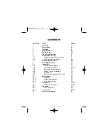
CONTENTS

SECTION

TITLE

PAGE

Warranty

1

1

Description

2

2

Features

2

3

Specifications

2-4

4

Safety Rules

5-6

5

Front Panel Controls

7

6

Preparation for Use

7

6.1

Unpacking and Contents Check

7

6-2

Pre-Operation Procedure

7-8

7

Battery Replacement

8-9

8

Fuse Replacement

10

9

Operation

11

9.1

Voltage Measurements

11

9.2

Current Measurements

12-13

9.3

Resistance Measurements

13

9.4

Battery Test Measurements

13

9.5

Diode Tests

14

9.6

Non Contact Voltage (NCV) Tests

14

10

Maintenance

15

10.1

Cleaning

15

10.2

Battery Replacement

15

10.3

Fuse Replacement

15

11

Calibration

16-17

11.1

Calibration procedure

17-18

12

Diagrams

19

12.1

Circuit Diagram

19

12.2

Parts List

20-21

13

Return For Repairs

21

DM4400 04_06  5/3/06  1:10 PM  Page 3

Содержание DM-4400A

Страница 1: ...prevented by any printed word and may cause injury and or equipment damage Please follow all these instructions and measurement procedures faithfully and adhere to all standard industry safety rules and practices The Professional s Choice 2150 Joshua s Path Suite 302 Hauppauge New York 11788 1 800 645 5398 631 231 7050 Fax 631 434 3128 DM4400 04_06 5 3 06 1 10 PM Page 2 ...

Страница 2: ...ement 10 9 Operation 11 9 1 Voltage Measurements 11 9 2 Current Measurements 12 13 9 3 Resistance Measurements 13 9 4 Battery Test Measurements 13 9 5 Diode Tests 14 9 6 Non Contact Voltage NCV Tests 14 10 Maintenance 15 10 1 Cleaning 15 10 2 Battery Replacement 15 10 3 Fuse Replacement 15 11 Calibration 16 17 11 1 Calibration procedure 17 18 12 Diagrams 19 12 1 Circuit Diagram 19 12 2 Parts List ...

Страница 3: ...nc shall be limited to the repair or replacement at its sole option of any defective product THIS WARRANTY AND THE OBLIGATIONS AND LIABILITIES OF SELLER THEREUNDER ARE EXCLUSIVWE AND IN LIEU OF AND BUYERS HEREBY WAIVES ALL OTHER REMEDIES EXPRESS WARRANTIES GUARANTEES OR LIABILITIES OF AND FOR INCIDENTAL OR CONSEQUENTAIL DAMAGES OR WHETHER OR NOT OCCASIONED BY S SELLER S NEGLIGENCE THIS WARRANTY SH...

Страница 4: ...c overload protection against accidental application of voltage to resistance and continuity circuits combined with its rugged construction make it a durable and reliable instrument Sec 2 FEATURES Pocket size Simple Operation 1000 hour battery life 10A DC AC Range Recessed safety designed input terminals Built in tilt stand Overload protection on all ranges Diode test function Non contact Voltage ...

Страница 5: ...0g including battery RANGES DC Voltage 3 Range Resolution Accuracy 18 C to 28 C Input Impedance 200mV 100µV 2 0 of rdg 4d 10MΩ 2V 1mV 0 5 of rdg 4d 20V 10mV 200V 100mV 600V 1V Normal Mode Rejection Ratio Greater than 46dB at 50 Hz 60Hz 1K unbalance Overload Protection 600VDC or AC rms for 1 minute AC Voltage Average Responding Calibrated in RMS of Sine Wave Range Resolution Accuracy 18 C to 28 C I...

Страница 6: ...sed Range Resolution Accuracy 18 C to 28 C Full Scale Burden Voltage 2mA 1µA 1 0 of rdg 4d 0 25V 200mA 100µA 10A 10mA 3 0 of rdg 1d 1 2V Range Resolution Accuracy 18 C to 28 C Open Circuit Voltage 200 10mΩ 1 2 of rdg 4d 0 45V 2K 1Ω 1 2 of rdg 1d 20K 10Ω 200K 100Ω 2000K 1KΩ 20M 10KΩ 3 0 of rdg 5d Diode Check Overload Protection 250VDC or peak AC Electronic No fuse blow Range Test Current Open Circu...

Страница 7: ...ng to take measurements 5 Never replace the protective fuse inside the DMM with any other than the Sperry Part number specified or approved equal 6 Remember Think Safety and Act Safely 7 When testing for the presence of voltage make sure the voltage function is operating properly by reading a known voltage in that range before assuming that a zero reading indicates a no voltage condition 8 Calibra...

Страница 8: ...NCV Sensor End 6 Fig 1 Non Contact Voltage Function Digital Display Input Terminals Range Selector Switch DM4400 04_06 5 3 06 1 10 PM Page 9 ...

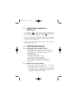
Страница 9: ... ready to use Check the following contents list when unpacking If any pieces are missing notify the distributor you purchased the instrument from or Sperry Instrument Inc Operating Instructions 415 Test Leads TL 54 one black one red 9V Transistor type Battery See Battery replacement section 10 2 for proper installation One Fuse installed one spare Fuse Part F 17 0 5A 250V 5mm X 20 mm fast acting S...

Страница 10: ...s are changed The maximum display reading is 1999 The 200DCV range will actually only read 199 9Vdc We call this the 200DCV range for convenience only 6 You can now check the decimal point on each range by referring to sec 3 Specifications where the ranges are all listed Refer to the Range and Resolution columns to compute the decimal point location 7 If any abnormal conditions exist do not attemp...

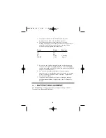
Страница 11: ... then from the instrument 2 Turn the range switch to the OFF position 3 Slide off the back case battery cover 4 Remove the battery from the compartment and unsnap the battery connector See Fig 2 5 Replace the battery with a 9V transistor type battery NEDA 1604 For maximum battery life alkaline cells are recommended 6 Reverse the above procedure to complete replacement 9 Fig 2 9V Battery DM4400 04_...

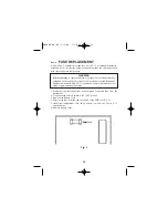
Страница 12: ...t the test leads from the instrument Replace the fuse with Part F 17 or approved equal only Always use fast acting high interrupting type fuses 1 Disconnect the test leads from any energized circuit and then from the instrument 2 Turn the range selector switch to the OFF position 3 Remove the battery cover 4 Remove the fuse from the clip on the end of the PCB See Fig 5 5 Install the replacement fu...

Страница 13: ... arc voltage is to be measured CAUTION To avoid possible electric shock instrument damage and or equipment damage do not attempt to take any voltage measurements if the voltage is above 600Vdc 600Vac or if the voltage is unknown 600Vdc and 600Vac is the maximum voltages that this instrument is designed to mea sure The COM terminal potential should not exceed 500V measured to ground 3 Apply the tes...

Страница 14: ...e circuit 4 If the reading is less than 0 20 Amps you can switch to a lower range for greater accuracy If not you have completed your measurement and skip to step 7 CAUTION Before changing ranges always de energize the circuit completely An open circuit exists between the test leads during range change on the DMM 5 To change to a lower range move the red test lead to the mA jack on the DMM and swi...

Страница 15: ...rument damage and or equipment damage do not connect the COM and V Ω terminals to cir cuits having a potential difference exceeding 250VDC AC Do not con nect the COM terminal to potentials exceeding 500V to ground 3 Completely de energize the circuit or device which is to be measured Connect the test leads to the device the red test lead is positive with respect to the black test lead A reading of...

Страница 16: ...TING A RANGE The meter defaults to autorange when you turn it on In autorange the meter selects the range automatically The Meter also has a manual range mode In manual range you select and lock the meter in arange To maually select a range Press RANGE button to hold the selected range Subsequently pressing the RANGE button will select each range in sequence from the lowest to highest range Hold t...

Страница 17: ...r the interior of the instrument while drying Sec 10 2 BATTERY REPLACEMENT Required when appears on display or nothing appears See BATTERY REPLACEMENT in section 7 Sec 10 3 FUSE REPLACMENT Required when current ranges other than 10Aac dc range do not function See FUSE REPLACEMENT in section 8 Sec 11 CALIBRATION Calibration on these meters should be performed every year This can be done by sending ...

Страница 18: ...qualified in electronics and electronic equipment service DO NOT attempt this procedure if not qualified WARNING Do not attempt calibration or service unless another person capable of rendering first aid and resuscitation is present 16 Fig 4 DM4400 04_06 5 3 06 1 10 PM Page 19 ...

Страница 19: ...ings should be within specification 0 5 1 digit 6 There is no adjustment for ACV Calibrate DCV first 7 Carefully inspect the ACV ranges Your readings should be within 1 2 4 digits of the ACV calibration source 8 Set the output of the DC calibrator for 1 9 0 02 and connect it to the 10A and COM input terminals 9 Adjust R001 shunt resistor until the display reads 1 9A 10 If the reading is over 1 9A ...

Страница 20: ...Sec 12 DIAGRAMS Sec 12 1 CIRCUIT DIAGRAM 18 Note Subsequent revisions to this document may exist Use for general references only DM4400 04_06 5 3 06 1 10 PM Page 21 ...

Страница 21: ...MD R014 1 6MD SMD R015 5 9MF SMD R015X 10MF SMD R016 R44 R92 100KJ X3 SMD R021A B C D E 2MF X5 SMD R022 1 11IMB SMD R023 10IKB SMD R024 10KD SMD R024 10KD SMD R025 1KB SMD R10 R46 RD 1MJ X3 SMD R11 1MJ SMD 1 2W R12 R21 R25 300KJ X3 SMD R13 560J SMD R20 R91 22MJ X2 SMD R22 R24 10KF X2 1 4W C R23 9KF 1 4W C R40 1KF SMD R41 VR 5K SMD R42 16 9KF SMD R43 3MJ SMD R1 R45 R91 R99 1KJ X4 SMD R90 2 7MJ SMD ...

Отзывы: