background image


Page 41 of 53 

SHENZHEN SPEEDLEADER TECHNOLOGY CO.,LTD.    LED  Video Processor  

in the manner of 4*2. 

LED sending card 

Support 1280*1024 at 

maximum. 

LVP6000 Video 

splicer 

A single LVP6000 can splice two LED video walls, so one LVP6000, two sending cards 

and two LED video walls form a splicing unit. 

One Splice Unit

A

B

Sending Card

LED

Display

1

LVP6000

O

U
T

P
U
T

Sending Card

LED

Display

2


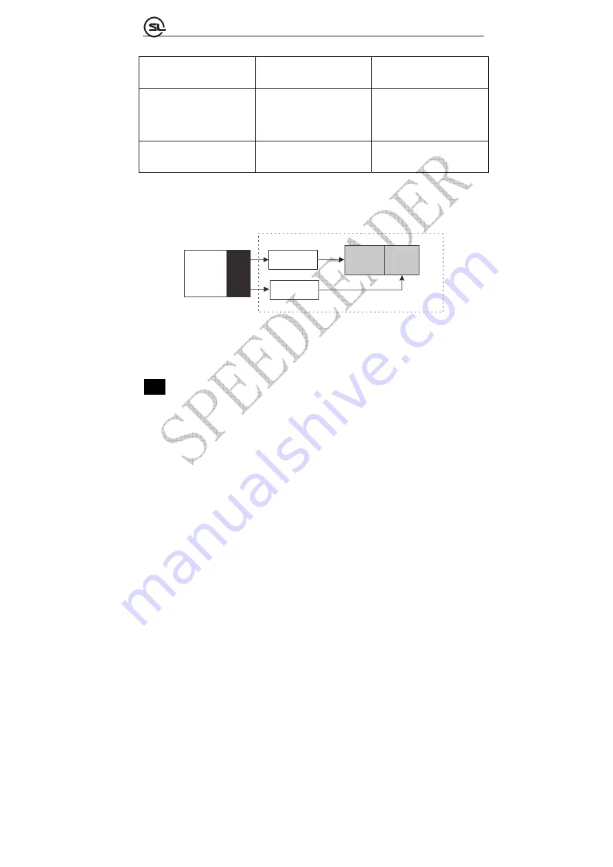
        Fig. 5-3 Schematic Diagram of LVP6000 Single-machine Splice Connection 

Note

:

 For connection of multi-machine splicing, the signal distributor shall be used to 

input the signal to the four sets of LVP6000 equipment. 

Operating steps: 

 Set single-machine connection 

Before the multi-machine splicing, each set of equipment shall be set and 

connected as shown in above Fig. to form a splicing unit. The two channels of DVI 

output of each LVP6000 are respectively connected with the LED sending cards; the 

Содержание LVP6000

Страница 1: ...User Manual LVP6000 Video Processor Seamless Switcher SHENZHEN SPEEDLEADER TECHNOLOGY ...

Страница 2: ...finitions 10 Operation 10 Mode descriptions of LVP6000 10 Introduction to front panel and keys 11 Menu system overview 16 Default menu introductions 17 Main menu introductions 19 Image quality menu 20 Crop menu 21 Output menu 22 Switcher mode 22 Splicing mode 23 Resoluting mode 23 Splice menu 26 Effect menu 28 Function menu 30 Advanced menu 32 System menu 32 Shortcut menu 33 ...

Страница 3: ...ENZHEN SPEEDLEADER TECHNOLOGY CO LTD LED Video Processor Splice operation 37 Setting and application of single machine splice 37 Setting and application of multi machine splice 39 Specifications 46 Troubleshooting 52 ...

Страница 4: ... If there is the content updating the company will not make further notice Unless there is a special agreement this manual is only taken as an instruction and all statements and information will not constitute a guarantee of any kind Brand Royalty VGA and XGA are the registered trademarks of IBM Corporation VESA is a trademark of the Video Electronics Standards Association The logo of HDMI and Hig...

Страница 5: ...uipment in the place which has the possibility for accidental collision or vibration and reinforcement processing is necessary in the vibration place When you use the equipment please make sure that there are no objects such as water and metal objects inside the equipment Otherwise it will damage the equipment and cause a fire If there is any irregularity or abnormality for the equipment please im...

Страница 6: ...e resolution of input signal up to 4K 2K and the output up to 4K 1K and it provides a perfect solution to the demands of high quality point to point applications of automobile exhibitions and high end conferences etc LVP6000 is also a seamless switcher with rich switching effects and preview output The original knob switching mode and rich switching effects can meet the demands of various advanced...

Страница 7: ...wo channels outputs for preview A and program B each output applies DVI I and DVI D interface which can realize two channel DVI and one channel VGA using DVI to VGA connector to connect the DVI I interface and meet more device attachment The user can determine seamless switching and effect switching of any channel at random The user can set any two input video into preview and program output and a...

Страница 8: ...n finish complex settings Rich physical interfaces are provided to meet the requirements of the common output equipment And the rotary knob can adjust relevant parameters of the picture quickly which is convenient for the users Installation Install LVP6000 The user can choose whether to install LVP6000 to the rack or flight case LVP6000 is a standard 1 5U chassis with the size of 6 5cm Height x 44...

Страница 9: ...000 Rear Panel Video input VID1 VID2 2 channel composite video input port BNC seat VGA1 VGA2 2 channel VGA input port DB15 seat DVI1 DVI2 DVI3 3 channel DVI input port DVI I seat HDMI 1 channel HDMI input port HDMI seat DP 1 channel DP input port DP seat SDI optional 1 channel SDI input port BNC seat Communication interface RS 232 RS 232 interface DB9 seat ...

Страница 10: ...usually B OUTPUT PROGRAM Program output interface which output to an LED sending card or a projector usually Two DVI I seats are employed which can output DVI and VGA signals at the same time When VGA signals are output a DVI VGA adapter shall be used to connect the seats to the DVI I interface Audio interface L1 IN R1 IN L2 IN R2 IN Two groups of audio input interfaces L OUT R OUT One group of au...

Страница 11: ... default menu Program signal Signals name displayed in the program area at default menu Preview picture Picture connected by the preview output PREVIEW in switcher mode Program picture Picture connected by the program output PROGRAM in switcher mode Spliced picture Picture spliced by the A output or the B output interface in splicing mode PIP picture Picture overlaid on the program or spliced pict...

Страница 12: ...ely to realize the picture splicing function of the two LED screens Introductions to Front Panel and Keys A 240 64 LED is adopted by the LVP6000 processor to indicate the current state menu selection data state and other parameters Background lights of the keys can reflect the current input selection and operation etc Hence the user can operate the whole menu system easily through the keys and rot...

Страница 13: ...n or realize other functions 3 Press MENU key at the default menu can enter the main menu interface RETURN SHIFT key 1 Press the key can return to the upper menu 2 It can be matched with the keys in INPUT area to realize program input video switching black screen output and screen freeze detailed in INPUT area as a combination key Note Operation instructions for combination key formed by SHIFT oth...

Страница 14: ...o the black screen Press the BLACK key again can cancel the black screen output When the BLACK key is enabled the key light is on 2 Press SHIFT BLACK key makes the program picture to the black screen 3 Erase function can be realized in PRESET state Input channel key 1 Input channel function PREVIEW channel switching Press the corresponding channel key in the area the light of the key is on PROGRAM...

Страница 15: ...menu PART Switch to part or full screen Part screen Background light is on Full screen Background light is off AUTO Auto calibrate VGA signal of the preview It be carried out only when the preview signal is the VGA and the valid signal Background light is on when the AUTO key is pressed and off after calibration PRESET Enter PRESET mode and press RETURN or PRESET key to exit the mode After enterin...

Страница 16: ...des Switcher mode Splicer mode FADE Switch between the preview picture and the program picture Switch the preview signal to the spliced picture PIP Add the PIP picture on the program picture Add the PIP signal to the spliced picture TITLE Key the preview picture and add the preview picture to the program picture Key the preview signal and add to the spliced picture EFFECT area The area includes FA...

Страница 17: ...the rotary knob the switching between the pictures can be fixed at a specific intermediate state thus realizing the switching effect more flexibly Note Rotating the knob to the intermediate state indicates that the picture is switched to the intermediate state Tapping TAKE or CUT key can finish the rest switching process Now the current scale of the rotary knob has no effect to the switching state...

Страница 18: ... on multi machine splicing for more information the default menu is as shown in Fig 4 3 FADE 0 5S PREVIEW PROGRAM VGA1 DVI1 1366x768 60 No Sync 0 Fig 4 3 Default Menu The default menu can be divided into four areas namely preview area left part program area right part switching speed middle upper part and effect mode area middle lower part Preview area Display the preview video name and resolution...

Страница 19: ...ime Effect mode area Upper line displays the current effect mode FADE PIP and TITLE Lower line displays the effect switching time 0 5S Note The effect switching time can be adjusted directly by the knob When the multi machine splicing method of the LVP6000 is on the default menu is as shown in the Fig 4 4 INPUT OUTPUT VGA1 A 1920x1080 1366x768 60 SPLICE B 1920x1080 UnEqual Fig 4 4 Default Menu in ...

Страница 20: ... the MENU key in the default menu can enter the main menu interface Fig 5 2 shows the first level menus of the main menu system on the LCD display screen There are eight first level submenus in the main menu including picture quality crop output splicing effect function advanced and system The user can rotate and tap the MENU key to quickly select and enter the next menus IMAGE OUTPUT CAPTURE SPLI...

Страница 21: ...TITLE mode y FUNC VGA DP HDMI DVI Flip Hot Backup settings y ADVANCE Contrast mode motion mode black extend DNR MPEG NR functions y SYSTEM OSD language system version fan switch and system reset function Image quality menu PORT Brightness Contrast Color Sharpness Color TEMP Gain Red Green Blue Offset Red Green Blue Reset PREV 50 50 50 12 Normal 256 256 256 0 0 0 The image quality menu is mainly us...

Страница 22: ...een and Blue range 0 256 adjusting the white balance will set the Color TEMP as User y RESET Initialize above parameters of the selected port Crop menu Port Crop Width Crop Height H Start V Start Reset Prev 1920 100 1080 100 0 0 The crop function can capture any part and any position of the input video to display y PORT Port can be adjusted only when PIP is on when the splicing mode In other condi...

Страница 23: ...UT TIMING Set output resolution the output resolution can set as switcher mode or splicer mode Switcher mode This mode is applied to preview and program picture output Fig 4 6 and is precisely a seamless switcher with rich switching effect Generally the preview output is connected with a monitor and the program output is connected with an LED screen thereby realizing the seamless switching perfect...

Страница 24: ...n or equal to real resolution of the LED screen both horizontal resolution and vertical resolution are greater than or equal to the real resolution and finally adjust the window parameters below Note When the resolution of the LED display screen is relatively small we suggest using the common resolution and when length width ratio of the resolution is too large or small we suggest using the user r...

Страница 25: ...he Width Height H Start and V Start are respectively adjusted to 800 600 0 and 0 the full picture will appear on the LED screen PART OR FULL The default is the full Options Full and part Full The LED screen displays the whole picture Part The LED screen displays a part of the picture Example When the resolution of the LED display screen is 800 600 choose the switcher mode with the output resolutio...

Страница 26: ...the menu in the splicer mode the two outputs are respectively connected with an LED display screen realizing the horizontal splicing of the two display screens In view of this the width adjustment involves in A output width and B output width and the horizontal start adjustment involves in A output horizontal start and B output horizontal start However other parameters are the same When the two gr...

Страница 27: ... LED screen Splice function can be applied to various LED splicing systems To realize the multi machine cascade each equipment s resolution must be set as splice mode OUTPUT Output Timing before entering the splicing menu The splice menu include Off Equal and Unequal Equal splicing refers to the horizontal pixels and vertical pixels of each part of the spliced video wall are equal Unequal splicing...

Страница 28: ...P6000 equipment in splicing calculation order for the positions is from left to right and top to bottom The following example describes above three parameters in 2 2 and 1 3 splicing in details Example 1 1 2 3 4 2x2 1 1 2 3 3x1 Fig 4 11 Example of LVP6000 Multi machine Equal Splicing H Splice Unit 2 when 2 2 splicing 3 when 3 1 splicing V Splice Unit 2 when 2 2 splicing 1 when 3 1 splicing Splice ...

Страница 29: ... of the current output in the spliced wall y V Splice Pos Vertical start pixel of the current output the spliced wall y For splicing operation the following sections will illustrate it explicitly Effect menu For different effect modes the effect menus are also different Press FADE PIP and TITLE in EFFECT area on the key press panel can switch to the corresponding effect mode The effect menus at di...

Страница 30: ...width of PIP s resolution y HEIGHT Default the height of PIP s resolution Range 96 the height of PIP s resolution y H START Default 0 Range 0 the width of PIP s resolution width y V START Default 0 Range 0 the height of PIP s resolution height y Color key options Black red green and blue Color key is the effect that the image color input by the preview channel subtracts the designated color which ...

Страница 31: ... switch to TITLE mode tap TITLE shortcut key firstly and then set the preview channel and program channel and tap CUT key or TAKE key to realize the image mating function Function menu VGA SETTING SUBMENU Port Auto Adjust H Position V Position H Clock Clock Phase PREV 0 0 0 0 For the VGA signal the position clock and phase parameter can be calibrated automatically or adjusted manually When the VGA...

Страница 32: ... 1280 1024 60 1680 1050 60 1920 1080 60 and 1920 1200 60 and User EDID DVI setting submenu EDID Output EQ y EDID EDID setting of the DVI channel including five common EDID of 1024 768 60 1280 1024 60 1680 1050 60 1920 1080 60 and 1920 1200 60 and User EDID y Output EQ HDMI setting submenu y EDID EDID setting of the HDMI channel including three common EDID of 720P 60 1080P 60 and 4K 2K 30 and User ...

Страница 33: ...ntrast PT Default Natural options Peak Natural Dynamic and Normal y Motion Mode Default Normal options Normal and Auto y Black Extend Default Off options Off Low Normal and high y DNR Default Off options Off Low Normal and High y MPEG NR Default Off options Off Low and High System menu OSD Language System Version Fan Switch Reset CH ENG ON y OSD Language Set the menu language including Chinese and...

Страница 34: ... is used for saving and calling the scene mode Through saving and calling scene parameters can be rebuilt quickly avoiding the repeated and complex setting Descriptions on saving parameters When the preset scene is saved the crop parameter output window parameter and effect mode are saved The following table illustrates the channels for saving the preset scene at different modes FADE PIP Switcher ...

Страница 35: ...ground template 1 as shown in above Fig indicate that the template has saved However the black characters on white background template 2 0 refer to the template is empty cannot be called In PRESET mode SAVE ERASE and numeric keys can be operated to realize all functions Through the SAVE and ERASE keys read save and erase functions can be switched and furthermore the templates can be operated by th...

Страница 36: ... the selected effect key will pop out the corresponding shortcut menu Press another effect key will switch to another effect mode For example if FADE effect is selected now press FADE key will pop out the FADE shortcut menu FADE shortcut menu When output resolution is set to the splicer mode the shortcut menu only displays effect switching time option However when the output resolution is set to t...

Страница 37: ...ight H Start V Start 960 540 0 0 y WIDTH Default the width of PIP s resolution Range 192 the width of PIP s resolution y HEIGHT Default the height of PIP s resolution Range 96 the height of PIP s resolution y H START Default 0 Range 0 the width of PIP s resolution width y V START Default 0 Range 0 the height of PIP s resolution height ...

Страница 38: ...ut menu Auto Adjust doing Press AUTO key can auto calibrate VGA signal of preview window After automatic calibration it will go back to the default menu automatically More functions about VGA automatic calibration go to FUNC VGA setting Splice operation Splice is divided into single machine splice and multi machine splice Setting and application of single machine splice 1 Set the output resolution...

Страница 39: ...er Quantity LED video wall A 1152 1024 LED video wall and a 960 1024 LED video wall are spliced into the 2112 1024 LED video wall in the manner of 2 1 2 LED sending card Support 1280 1024 at maximum 2 LVP6000 Video splicer 1 Splice operation 1 Hardware connection as shown in the following Fig A B LED Display 1 LED Display 2 LVP6000 1152 960 1024 O U T P U T Sending Card Sending Card Fig 5 1 Schema...

Страница 40: ...single machine splice The multi machine splice can be classified into equal splicing and unequal splicing in which the equal splice refers to the horizontal pixels and vertical pixels of each part of the spliced video wall are equal the unequal splice refers to the pixels of each part of the video wall may be unequal Here we will focus on the equal splicing and unequal splice of LED video wall Con...

Страница 41: ... DP INPUT Fig 5 2 Schematic Diagram of LVP6000 Multi machine Splice Connection Setting before splicing Before multi machine splicing 1 Set the output resolution to the splicer mode 2 Set the output parameter so that the whole picture can be displayed on the two LED screens of each set of equipment 1 Example of 2 2 equal splicing of LED video wall Table 5 2 Current Equipment and Relevant Parameters...

Страница 42: ...1 LVP6000 O U T P U T Sending Card LED Display 2 Fig 5 3 Schematic Diagram of LVP6000 Single machine Splice Connection Note For connection of multi machine splicing the signal distributor shall be used to input the signal to the four sets of LVP6000 equipment Operating steps Set single machine connection Before the multi machine splicing each set of equipment shall be set and connected as shown in...

Страница 43: ...put HStart B Output HStart V Start Part or Full Reset 1280 1280 896 0 0 0 Full Set multi machine connection Connect the four sets of equipment input the signal and operate as per the step 1 Set sending cards Set relevant parameters of the eight sending cards respectively so that the eight spliced walls can work separately For detailed operation of the sending cards please refer to instruction manu...

Страница 44: ... 2 4 LVP6000 1 LVP6000 2 LVP6000 3 LVP6000 4 Fig 5 4 Schematic Diagram of LVP6000 Multi machine Equal Splice Connection LVP6000 1 LVP6000 2 LVP6000 3 LVP6000 4 Splice Unit 1 Splice Unit 2 Splice Unit 3 Splice Unit 4 Fig 5 5 Schematic Diagram of Multi machine Equal Splice Connection 2 Example of unequal splicing of LED video wall Table 5 3 Current Equipment and Relevant Parameters Equipment name mo...

Страница 45: ...000 are respectively connected with the LED sending cards the LED sending cards are connected to each part of the spliced wall by CAT5 cables and the output resolution shall be set to 1920 1080 60 splicing mode Adjust other parameters as shown in the Fig below Output Timing A Output Width B Output Width Height A Output HStart B Output HStart V Start 1152 1152 1024 0 0 0 Output Timing A Output Widt...

Страница 46: ... cards please refer to instruction manual provided by the sending card manufacturer Open the multi machine splicing and set the splicing menu as shown in the Fig below Splice Way H Total Size V Total Size H Splice Pos V Splice Pos UnEqual 4224 1024 0 0 LVP6000 1 Splice Way H Total Size V Total Size H Splice Pos V Splice Pos UnEqual 4224 1024 2304 0 LVP6000 2 Fig 5 7 Schematic Diagram of LVP6000 Mu...

Страница 47: ... quantity 1 Connector DP Signal standard DP1 2 downward compatibility Supported resolution VESA standard PC to 3840 2160 DP video input Input quantity 1 Connector DP Signal standard DP1 2 downward compatibility Supported resolution VESA standard PC to 3840 2160 HDMI video input Input quantity 1 Connector HDMI ...

Страница 48: ...20 1200 HD to 4K 2K 30Hz DVI video input Input quantity 3 Connector DVI I Signal standard DVI I 1 0 Supported resolution VESA standard PC to 1920 1200 HD to 1080p VGA video input Input quantity 2 Connector DB15 Signal standard R G B Hsync Vsync 0 to1Vpp 3dB 0 7V Video 0 3v Sync 75 ohm black level 300mV Sync tip 0V Supported resolution VESA standard PC to 1920 1200 ...

Страница 49: ...nnector BNC Signal standard PAL NTSC SECAM 1Vpp 3db 0 7V Video 0 3v Sync 75 ohm Supported resolution 480i 576i 3G SDI video input optional Input quantity 1 Connector BNC Signal standard SD SDI HD SDI 3G SDI Supported resolution 1080p 60 50 30 720p 60 50 1080i 60 50 625 525 line 3G SDI video looping out optional ...

Страница 50: ...DI HD SDI 3G SDI Supported resolution 1080p 60 50 30 720p 60 50 1080i 60 50 625 525 line Preview PREVIEW video output Output quantity One channel of VGA two channels of DVI Connector DVI I Signal standard VGA standard R G B Hsync Vsync 0 to1Vpp 3dB 0 7V Video 0 3v Sync 75 ohm black level 300mV Sync tip 0V DVI standard DVI1 0 ...

Страница 51: ...920 1080 60Hz 3840 1200 60Hz A B 2304 1920 60Hz A B Custom resolution A B Program PROGRAM video output Output quantity One channel of VGA two channels of DVI Connector DVI I Signal standard VGA standard R G B Hsync Vsync 0 to1Vpp 3dB 0 7V Video 0 3v Sync 75 ohm black level 300mV Sync tip 0V DVI standard DVI1 0 ...

Страница 52: ...1080 60Hz 3840 1200 60Hz A B 2304 1920 60Hz A B Custom resolution A B Equipment parameters Weight 4 5kg Dimension 6 5cm height 44cm width 32cm depth Input power 100VAC 240VAC 50 60Hz Maximum power 35W Working temperature 0 45 Storage humidity 10 90 Specification parameters are subject to improvement without notice ...

Страница 53: ... no image output Check whether the signal is connected correctly Check whether the equipment supports the resolution and refresh the frequency Reset the equipment to factory default settings y VGA picture cannot be displayed on the full screen or is deflected Check whether VGA wire is up to standard or overlong Open the menu System VGA settings Automatic adjustment and hit VGA automatic adjustment...

Страница 54: ...sor I n d u s t r y S a l e s a n d S e r v i c e H o t l i n e 4 0 0 6 2 8 6 9 5 9 SHENZHEN SPEEDLEADER TECHNOLOGY CO LTD Tel 0755 26588939 Fax 0755 26586619 Post Code 518052 Address 6 F Bldg 78 Majialong Industrial Zone Nanshan District Shenzhen http www speedleader cn ...

Отзывы: