Spectra Powerbox 110 Series Скачать руководство пользователя страница 73

Spectra


GmbH


&


Co.


KG

[email protected]

User


Manual

Spectra


PowerBox 110


Series

Version


1.1

April


2019

73

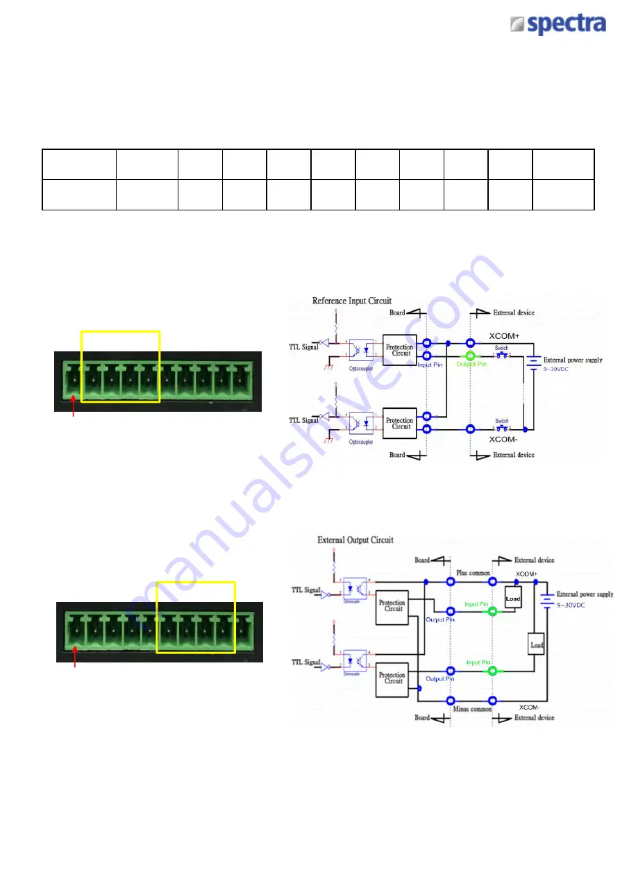
5.2.1 DIO Connector Definitions 

DIO1: Digital Input Connector

Connector Type: Terminal Block 1X10 10-pin, 3.5mm pitch

Pin

1

2

3

4

5

6

7

8

9

10

Definition

XCOM+

DI1

DI2

DI3

DI4

DO1

DO2

DO3

DO4

XCOM-

Pin 1

DI

Pin 1

DO

Содержание Powerbox 110 Series

Страница 1: ...SPECTRA POWERBOX 110 SERIES USER MANUAL Version 1 1 April 2019...

Страница 2: ...atures 12 1 5 Hardware Specification 13 1 6 System I O 14 1 7 Mechanical Dimension 16 Chapter 2 Switches and Connectors 2 1 Jumper Settings 18 2 2 Location of the Switches and Connectors 18 2 2 1 Top...

Страница 3: ...uration 53 4 3 9 USB Configuration 55 4 4 Chipset Setup 56 4 4 1 North Bridge 56 4 4 2 South Bridge 57 4 4 3 South Cluster Configuration 58 4 5 Security Setup 61 4 6 Boot Setup 62 4 7 Save Exit 63 Cha...

Страница 4: ...ives if it has a CE marking For computer systems to remain CE compliant only CE compliant parts may be used Maintaining CE compliance also requires proper cable and cabling techniques Revision Copyrig...

Страница 5: ...A Instruction Customers must fill in Spectra Return Merchandise Authorization RMA Request Form and obtain a RMA number prior to returning a defective product to Spectra for service Customers must coll...

Страница 6: ...nformation to complete a task easily NOTE Technical Support and Assistance 1 Visit our website at www spectra de where you can find the latest information about the product 2 Contact our technical sup...

Страница 7: ...ent rating of the cord must be greater than the voltage and current rating marked on the product 9 Position the power cord so that people cannot step on it Do not place anything over the power cord 10...

Страница 8: ...ctor 1 6 Screw Pack 1 7 Remote Power On Off Terminal Block Connector 1 8 Wall Mounting Kit 1 Note Notify your sales representative if any of the above items are missing or damaged Ordering Information...

Страница 9: ...e with 8x Optical Isolated DIO 4 in 4 out 1xUniversal Bracket with DIO Cutout for PowerBox 100 110 series PB 100 LPT PS2 CMI Module with 1x LPT Port 1x PS 2 1x Universal Bracket with PS 2 LPT Cutout f...

Страница 10: ...Product Introductions Chapter 1...

Страница 11: ...e design in an ultra compact aluminum housing Spectra PowerBox 110 is ideally for deployment in space constrained place and continuous operation under harsh environments 1 2 Highlights Triple Displays...

Страница 12: ...leron N3350 Processors Supports Triple Independent Display Supports PoE Function with optional CFM Module Supports CMI Interface for I O Expandability 1 x 2 5 SATA Drive Bay 1x mSATA Socket 2 x Full S...

Страница 13: ...CIe Socket 1x Control Function Module CFM Interface 1x Combined Multiple I O CMI Interface 1x SIM Socket 2x Antenna Holes Other Functions Watchdog Timer Software Programmable Supports 256 Levels Syste...

Страница 14: ...c In Used to connect a microphone Line Out Used to connect a speaker LAN Port 1 2 Used to connect the system to a local area network USB 3 0 Port Used to connect USB 3 0 2 0 1 1 device USB 2 0 Port Us...

Страница 15: ...splayPort DVI LPT PS2 VGA HDMI Do not change the CMI module by yourself it may cause damage to your Spectra PowerBox 110 Please contact with your regional dealer for more information about it DC IN Te...

Страница 16: ...a GmbH Co KG vertrieb spectra de User Manual Spectra PowerBox 110 Series Version 1 1 April 2019 16 1 7 Mechanical Dimensions Each of Spectra PowerBox 110 computers has the same mechanical dimension Un...

Страница 17: ...Switches and Connectors Chapter 2...

Страница 18: ...rtrieb spectra de User Manual Spectra PowerBox 110 Series Version 1 1 April 2019 18 2 1 Jumpers Settings Spectra PowerBox 110 is featured with jumper free design 2 2 Location of the Switches and Conne...

Страница 19: ...Spectra GmbH Co KG vertrieb spectra de User Manual Spectra PowerBox 110 Series Version 1 1 April 2019 19 2 2 2 Bottom View...

Страница 20: ...ess Socket mSATA PWR_SW1 Remote Power Button Connector DC_IN1 3 PIN DC 9 48V Power Input Connector MIC_IN1 Microphone in Jack LINE_OUT1 Audio Line out Jack LAN1 LAN2 RJ45 with LED Connector USB3_1 USB...

Страница 21: ...Mode Default 2 4 Definition of Switches AT_ATX AT ATX Power Mode Switch CLR_CMOS Clear CMOS Switch Switch Definition 1 2 Left Normal Status Default 2 3 Right Clear CMOS PWR_SW1 System Power Button Swi...

Страница 22: ...GND 30 SMB_CLK 5 NA 31 PETN0 USB3TN0 6 1 5V 32 SMB_DATA 7 NA 33 PETP0 USB3TP0 8 SIM_VCC 34 GND 9 GND 35 GND 10 SIM_DATA 36 USB_D 11 REFCLK 37 RESERVED 12 SIM_CLK 38 USB_D 13 REFCLK 39 RESERVED 14 SIM_...

Страница 23: ...2 3 3V 28 1 5V 3 NA 29 GND 4 GND 30 SMB_CLK 5 NA 31 PETN0 SATATN0 6 1 5V 32 SMB_DATA 7 NA 33 PETP0 SATATP0 8 NA 34 GND 9 GND 35 GND 10 NA 36 USB_D 11 REFCLK 37 GND 12 NA 38 USB_D 13 REFCLK 39 3 3V 14...

Страница 24: ...48V IN 2 Chassis GND 3 GND PWR_SW1 Remote Power On Off Connector Pin Definition 1 PWR_SW 2 GND Note Please do not apply power to the pins This port is used to connect a switch 1 2 1 2 3 LAN1 LAN2 LAN...

Страница 25: ...S485 Connector Connector Type 9 pin D Sub Pin RS232 Definition RS422 485 Full Duplex Definition RS485 Half Duplex Definition 1 DCD TX DATA1 2 RXD TX DATA1 3 TXD RX 4 DTR RX 5 GND 6 DSR 7 RTS 8 CTS 9 R...

Страница 26: ...System Setup Chapter 3...

Страница 27: ...nit to have the bottom side face up loosen the 4 screws of bottom cover and place them aside 3 1 Removing the Chassis Bottom Cover In order to prevent electric shock or system damage before removing t...

Страница 28: ...eb spectra de User Manual Spectra PowerBox 110 Series Version 1 1 April 2019 28 3 2 Removing the Chassis 1 Hold front and rear panel and lift up the body of unit vertically 2 Turn over the body of the...

Страница 29: ...ser Manual Spectra PowerBox 110 Series Version 1 1 April 2019 29 3 3 Installing the Antennas 1 Remove the antenna hole covers at back panel 2 Have antenna jack penetrate through the hole 3 Put on wash...

Страница 30: ...bH Co KG vertrieb spectra de User Manual Spectra PowerBox 110 Series Version 1 1 April 2019 30 4 Assemble the antenna and antenna jack together 5 Attach the RF connector at another end of cable onto t...

Страница 31: ...Mini PCIe Card on Bottom Side including Half Size Mini PCIe card 1 Turn over the body of unit Unscrew the 4 screws on HDD bracket and remove the bracket 2 Locate the Mini PCIe slots Please note that...

Страница 32: ...the Mini PCIe modules at 45 degree angle and insert it to the slot until the gold pated connector of module contacted firmly with the slot 4 Press down the module and use the two screws to fix the mo...

Страница 33: ...ft up the empty HDD bracket by unscrewing the 4 screws 2 Make the PCB side of the HDD face up place the HDD bracket on it Ensure the direction of bracket is correct and use 3 provided screws to assemb...

Страница 34: ...tra PowerBox 110 Series Version 1 1 April 2019 34 3 6 Installing a Half Slim SSD 1 Lift up the empty HDD bracket by unscrewing the 4 screws 2 Fasten the 4 copper pillars 3 Connect the Half Slim SSD to...

Страница 35: ...2019 35 3 7 Installing a SODIMM 1 Locate SODIMM socket 3 Press the module down until it s fixed firmly by the two locking latches on the sides 45 2 Tilt the SODIMM module at a 45 degree angle and inse...

Страница 36: ...User Manual Spectra PowerBox 110 Series Version 1 1 April 2019 36 3 8 Installing the Chassis 1 Hold the body of unit and make sure the both sides of front and rear panels are in the chassis grooves an...

Страница 37: ...pectra de User Manual Spectra PowerBox 110 Series Version 1 1 April 2019 37 3 9 Installing the Chassis Bottom Cover 1 Level the grooves on the cover at front and rear panels Put on the cover 2 Fasten...

Страница 38: ...ectra de User Manual Spectra PowerBox 110 Series Version 1 1 April 2019 38 3 10 Installing a SIM Card 3 Insert the SIM card 1 Loosen 2 screws on front panel to remove cover plate 2 SIM card slot is at...

Страница 39: ...The mounting holes are at the bottom side of system Use provided 4 screws to fasten the bracket with each side on system together Spectra PowerBox 110 offers Wall Mount that customers can install sys...

Страница 40: ...nt Bracket Spectra PowerBox 110 offers Side Mount that customer can install system to the right or left side of wall to create effectiveness of space 1 Place the side mount bracket on the bottom of sy...

Страница 41: ...Spectra GmbH Co KG vertrieb spectra de User Manual Spectra PowerBox 110 Series Version 1 1 April 2019 41 2 Fasten the screws through the bracket mounting hole to mount system on the wall...

Страница 42: ...3 13 VESA Mount Bracket 1 Provided below is the base of the system unit and screw holes specified to be mounted from VESA stand Spectra PowerBox 110 offers VESA Mount that customer can mount system wi...

Страница 43: ...Spectra GmbH Co KG vertrieb spectra de User Manual Spectra PowerBox 110 Series Version 1 1 April 2019 43 3 Provided below is completion of mounting with VESA stand...

Страница 44: ...ries Version 1 1 April 2019 44 3 14 DIN Rail Mount Bracket Spectra PowerBox 110 offers DIN Rail Mount that customer can install system on the DIN Rail 1 The mounting holes are at the bottom of system...

Страница 45: ...Side Mount Bracket Spectra PowerBox 110 offers DIN Rail Mount Clips and side mount bracket that customer can install system on the DIN Rail 2 Refer to section 3 12 Side Mount Bracket to install the mo...

Страница 46: ...BIOS Setup Chapter 4...

Страница 47: ...ys Move to select screen Move to select item Esc Quit the BIOS Setup Enter Select item Page Up Increases the numeric value or makes changes Page Down Decreases the numeric value or makes changes Tab S...

Страница 48: ...Del key to enter BIOS CMOS Setup Utility the Main Menu as shown below will appears on the screen Use arrow keys to move among the items and press Enter to accept or enter a sub menu System Date Set th...

Страница 49: ...ser Manual Spectra PowerBox 110 Series Version 1 1 April 2019 49 4 3 Advanced Setup This section allows you to configure and improve your system and allows you to set up some system features according...

Страница 50: ...not be effective with some OS ACPI Sleep State S3 Suspend to RAM Allows users to select the highest Advanced Configuration Power Interface ACPI sleep state that system will enter when suspend button...

Страница 51: ...S232 Allows you to select Serial Port Mode Configuration options RS232 RS422 RS485 Full Duplex RS485 Half Duplex Watch Dog Function You can setup the system watch dog timer a hardware timer that gener...

Страница 52: ...de User Manual Spectra PowerBox 110 Series Version 1 1 April 2019 52 4 3 3 Hardware Monitor This screen displays the current status of all monitored hardware devices components such as voltages tempe...

Страница 53: ...system from S5 soft off state Disabled Disables wake system from S5 Fixed Time Sets a fixed time HH MM SS to wake system from S5 Dynamic Time Sets a increase minute s from current time to wake system...

Страница 54: ...memory Active Processor Cores Enabled Number of cores to enable in each processor package Intel Virtualization Technology Enabled Enables or disables Intel Virtualization Technology Virtualization enh...

Страница 55: ...de User Manual Spectra PowerBox 110 Series Version 1 1 April 2019 55 4 3 7 Network Stack Configuration Network Stack Disabled Enables or disables UEFI Network Stack 4 3 8 CSM Configuration This option...

Страница 56: ...Network Do not launch Controls the execution of UEFI and Legacy PXE Network Preboot eXecution Environment option ROM Do not launch Disables option ROM execution UEFI Enables UEFI option ROM only Legac...

Страница 57: ...able or disable legacy USB support When set to Auto legacy USB support will be disabled automatically if no USB devices are connected XHCI Hand off Enabled Enables or disables XHCI USB3 0 hand off fun...

Страница 58: ...l Spectra PowerBox 110 Series Version 1 1 April 2019 58 4 4 Chipset Setup This section allows you to configure chipset related settings according to user s preference 4 4 1 North Bridge This section p...

Страница 59: ...to configure Operating System version to install Configuration options Windows Intel Linux Mini PCIE2 mSATA Switch Mini PCIE Allows you to change Mini PCIE2 as Mini PCIE or mSATA PSE Enable Selection...

Страница 60: ...Spectra GmbH Co KG vertrieb spectra de User Manual Spectra PowerBox 110 Series Version 1 1 April 2019 60 4 4 3 South Cluster Configuration PCI Express Configuration...

Страница 61: ...uto Allows you to select PCI Express port speed Configuration options Auto Gen1 Gen2 PCI Express Root Port 6 MiniPcie PCI Express Root Port 6 MiniPcie Enabled Enables or disables PCI Express Root Port...

Страница 62: ...will enter when power is resumed after a power failure G3 state Always on Enters to power on state Always off Enters to power off state Last state Enters to the last power state before a power failur...

Страница 63: ...4 5 Security Setup This section allows you to configure BIOS security settings Administrator Password Allows you to set Administrator Password to control access to the BIOS Setup utility User Passwor...

Страница 64: ...onfigure Boot settings Bootup NumLock State Allows you to set NumLock key to On or Off state when system boots up Quiet Boot Allows you to enable or disable Quiet Boot function Fast Boot Allows you to...

Страница 65: ...ing changes Discard Changes and Reset This item allows you to reset system setup without saving any changes Restore Defaults This item allows you to restore load default values for all the setup optio...

Страница 66: ...Product Application For PB 100 DIO Only Chapter 5...

Страница 67: ...configuration procedures must be followed in sequence 1 Enter the Extended Function Mode 2 Configure the configuration registers 3 Exit the Extended Function Mode The configuration register is used t...

Страница 68: ...mbH Co KG vertrieb spectra de User Manual Spectra PowerBox 110 Series Version 1 1 April 2019 68 5 1 1 3 Relative Registers To program the F81866A configuration registers the following configuration pr...

Страница 69: ...wice to enter Extended mode Select Logic Device WriteByte AddrPort 0x07 WriteByte dataPort 0x06 Select logic device 06h Output Input Mode Selection Set GP54 to GP57 input Mode WriteByte AddrPort 0xA0...

Страница 70: ...Select Logic Device WriteByte AddrPort 0x07 WriteByte DataPort 0x06 Select logic device 06h Output Input Mode Selection Set GP60 to GP63 output Mode WriteByte AddrPort 0x90 Select configuration regis...

Страница 71: ...teByte DataPort ReadByte DataPort 0x03 WriteByte AddrPort 0x61 Select configuration register 61h WriteByte DataPort ReadByte DataPort 0x20 Leave the Extended Function Mode WriteByte AddrPort 0xAA GPIO...

Страница 72: ...olated power in V XCOM 2XCOM Isolated power in V Isolated power in DC voltage 9 30V 4x Digital Input Source Type Input Signal Voltage Level Signal Logic 0 XCOM 9V Signal Low V 1V XCOM 9V V Signal Low...

Страница 73: ...PowerBox 110 Series Version 1 1 April 2019 73 5 2 1 DIO Connector Definitions DIO1 Digital Input Connector Connector Type Terminal Block 1X10 10 pin 3 5mm pitch Pin 1 2 3 4 5 6 7 8 9 10 Definition XC...

Страница 74: ...Optional Module Pin Definitions and Settings Chapter 6...

Страница 75: ...B 100 DP CMI Module with 1x Display Port 1x Universal Bracket with DP Cutout for PowerBox 100 110 series PB 100 DVI CMI Module with 1x DVI D Connector 1x Universal Bracket with DVI D Cutout for PowerB...

Страница 76: ...April 2019 76 6 2 Installing a PB 100 COM Module 1 Unscrew 2 screws to remove bracket from rear panel 3 Attach the PB 100 COM bracket and fasten 2 screws as marked on photo 2 Insert PB 100 COM module...

Страница 77: ...Type 9 pin D Sub Pin RS232 Definition RS422 485 Full Duplex Definition RS485 Half Duplex Definition 1 DCD TX DATA1 2 RXD TX DATA1 3 TXD RX 4 DTR RX 5 GND 6 DSR 7 RTS 8 CTS 9 RI 1 5 6 9 Function PIN C...

Страница 78: ...April 2019 78 6 3 Installing a PB 100 DIO Module 1 Unscrew 2 screws to remove bracket from rear panel 3 Attach the PB 100 DIO bracket and fasten 2 screws as marked on photo 2 Insert PB 100 DIO module...

Страница 79: ...1 April 2019 79 6 4 Installing a PB 100 DP Module 1 Unscrew 2 screws to remove bracket from rear panel 3 Attach the PB 100 DP bracket and fasten 2 screws as marked on photo 2 Insert PB 100 DP module v...

Страница 80: ...April 2019 80 6 5 Installing a PB 100 DVI Module 1 Unscrew 2 screws to remove bracket from rear panel 3 Attach the PB 100 DVI bracket and fasten 2 screws as marked on photo 2 Insert PB 100 DVI module...

Страница 81: ...81 6 6 Installing a PB 100 VGA Module 1 Unscrew 2 screws to remove bracket from rear panel 3 Attach the PB 100 VGA bracket fasten 2 screws and 2 D Sub jack screws as marked on photo 2 Insert PB 100 V...

Страница 82: ...April 2019 82 6 7 Installing a PB 100 HDMI Module 1 Unscrew 2 screws to remove bracket from rear panel 3 Attach the PB 100 HDMI bracket fasten 2 screws as marked on photo 2 Insert PB 100 HDMI module...

Страница 83: ...8 Installing a PB 100 LPT PS2 Module 1 Unscrew 2 screws to remove bracket from rear panel 3 Attach the PB 100 LPT PS2 bracket fasten 2 screws and 2 D Sub jack screws as marked on photo 2 Insert PB 100...

Страница 84: ...pril 2019 84 6 9 Installing CFM PoE Control Module 1 Locate the PoE connector on system motherboard as indicated 2 Insert the female connector of CFM PoE module to the male connector on system motherb...

Страница 85: ...110 Series Version 1 1 April 2019 85 4 Paste the heatsink onto the CFM PoE module carefully and fasten 2 screws to fix it 5 Paste the thermal pads onto the heatsink and coil carefully 3 Turn over the...

Страница 86: ...ell Wels Austria 43 0 7240 20190 info spectra austria at www spectra austria at Phone E Mail Web Spectra Schweiz AG Flugplatzstr 5 8404 Winterthur Switzerland 41 0 43 2771050 info spectra ch www spect...

Отзывы: