8999146EN: v1 26/02/2020
45
Original instructions (ENGLISH)
Website: www.spearheadmachinery.com
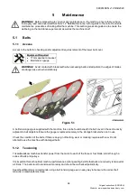
The Optikrik III belt tension gauge is supplied with the machine to easily carry out the tensioning of the various
belts.
WARNING!
Checking of belts and drive components should only be carried out with the tractors engine
switched off, starting key removed and the PTO shaft disconnected. Never attempt to run the machine
with the belt guard removed
– Replace the guard after tensioning before starting the machine.
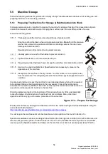
Item. Description.
A
Indicator Arm
B
Rubber Finger Loop
C
Pressure Pad
D
V-Belt
E
Belt Tension
Measurement Point
Figure 5.2
– Optikrik Belt Tension Gauge & Components
To correctly tension belts using the Optikrik III:
Position the Optikrik in the middle of the longest belt runs on each of the belt circuits. Take care to
ensure that the indicator arm (A) is pushed down into the gauge body. Align the gauge so that its body
is parallel with the sides of the belt.
Push down on the pressure pad (C)
slowly and firmly with one finger. When a “click” is heard/felt, stop
immediately and remove the gauge carefully to avoid disturbing the indicator arm.
Read and turn the gauge sideways if required, to ascertain the exact point where the top surface of the
indicator arm (A) crosses the scale (E). This is the given belt tension.
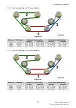
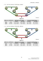
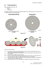
Tighten or slacken the belts as necessary following the guidance below and repeat the process again
on the other two belt circuits.
Equipment Required
•
19mm spanner or socket
•
Belt tension gauge or sonic meter

