background image


–13– Form 

#43219000 


Jan 09 

Item No. 

Part No. 

Description 

40714000 

Plenum Box Assembly 

41218000 

Emitter Kit (includes items 3 & 4) 

40446080 

End Gasket (Qty. 2) 

40446090 

Side Gasket (Qty. 2) 

40608000 

Screen Retainer (Qty. 2) 

40670030 

Reverb Screen (pilot) 

40710020 

End Reverb Baffle 

40621000 

End Flue Collar 

40616000 

Side Flue Collar 

10 40726000 

Venturi 

Assembly 

11 40666000 

Venturi 

Gasket 

12 03339020 

Plug, 

1/8 

13 

03338130 

Bushing, 1/2 x 1/8 

14 

03333100 

Nipple, 1/2 x 3" 

15 

03624320 

Main Burner Orifice (#32) Nat. Gas 

16 

03625450 

Main Burner Orifice (#45) LP Gas 

17 

40710010 

Reverb Baffle (notched) 

18 

30299020 

Gas Valve @ 6" WC - VS820A-1070 Nat. Gas 

19 

30299030 

Gas Valve @ 10" WC - VS820A-1120 LP Gas 

20 

40720000 

Reflector Assembly (pilot) 

21 

42431000 

Pilot Housing Assembly 

22 

42425000 

Radiation Shield (housing) 

23 

42421000 

Pilot Flue Baffle 

24 42424000 

Pilot 

Shield 

25 42434000 

Pilot 

Tubing 

26 

40706000 

Radiation Shield (pilot) 

27 

03462130 

Pilot Generator System - Nat. Gas 

28 

03462140 

Pilot Generator System - LP Gas 

29 

03463000 

Pilot Burner, Less Orifice (included in items #27 & #28) 

30 

03460030 

Pilot Orifice, TL020 - Nat. Gas (included in item #27) 

31 

03438020 

Pilot Orifice, TV011 - LP Gas (included in item #28) 

32 03378060 

Generator 

Cartridge, PG9 (included in items #27 & #28) 

33 

43219000 

Installation Manual (not shown) 


MODELS: RSCA6-

(N5A,L5) 

1

3,4

2

23

17

6

22

21

24

26

27-32

25

10

11

15,16

12

13

14

18,19

20

8

7

9

5

Содержание RSCA10

Страница 1: ...property of the owner Please present this manual to the owner when you leave the job site SWARNING Improper installation adjustment alteration service or maintenance can cause property damage injury or death Read the installation operation and maintenance instructions thoroughly before installing or servicing this equipment IMPORTANT SAVE THIS MANUAL FOR FUTURE REFERENCE SPACE RAY Post Office Box ...

Страница 2: ... not generally present as defined by OSHA acceptable limits and is intended for space heating non residential spaces SAFETY REQUIREMENTS The heater area must be kept clear and free from combustible materials gasoline and other flammable vapors and liquids This heater is designed for use with one type of gas LPG or Natural Make sure that the type of gas to be supplied to this heater matches that sh...

Страница 3: ...r Aircraft Hangars ANSI NFPA 88a latest edition Standard for Parking Structures and ANSI NFPA 88b latest edition Standard for Repair Garages with the following clearances a At least 10 feet above the upper surfaces of wings or engine enclosures of the highest aircraft that may be housed in the hangar and at least 8 feet above the floor in shops offices and other sections of hangars communicating w...

Страница 4: ...be damaged by temperatures 90ºF above ambient temperature It is the installer s responsibility to ensure that building materials with a low heat tolerance which may degrade at lower temperatures are protected to prevent degradation Clearances to combustibles are posted on the reflector near the control end of the heater In areas used for storage of combustible materials where they may be stacked b...

Страница 5: ...comfort and uniform energy distribution for complete building heating applications Consult your Space Ray representative for the particulars of your installation requirements 5 OPTIONAL PARABOLIC REFLECTOR EXTENSION ASSEMBLY The heater is completely factory assembled and requires no field assembly If the optional parabolic reflector extension is utilized locate and identify the end panels and side...

Страница 6: ...then a second stage regulator which corresponds to the supply pressure must be used 6 If a second stage regulator is used and gas seeps through it the redundant combination gas valve is designed to lock out Pressure build up in the supply lines prior to the heater must be released before proper heater operation 7 After all gas connections have been made make sure the heater and all gas outlets are...

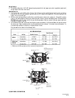
Страница 7: ... to decrease the gas pressure to the burner Replace the cover screw The gas pressures are shown in the following table GAS PRESSURE TABLE Supply Pressure Model Gas Type Manifold Pressure Minimum7 Maximum Natural Gas 3 5 W C 4 5 W C 14 0 W C RSCA3 Propane Gas 10 0 W C 11 0 W C 14 0 W C Natural Gas 6 0 W C 7 0 W C 14 0 W C RSCA6 and RSCA10 Propane Gas 10 0 W C 11 0 W C 14 0 W C 7 Minimum permissible...

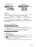
Страница 8: ...round 3 Amp Fuse GND burner CONNECTION WIRING DIAGRAMS chéma de circuit de connexion Ignition Module Honeywell S87C TRANSFORMER 120V PRIMARY 24V SECONDARY If any of the original wire as supplied with the appliance must be replaced It must be replaced with wiring material having a temperature rating of at least 105oC 18 AWG UL CSA 600V Type TEW When connecting the supply circuit to the heater wirin...

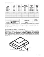
Страница 9: ...above and in the vicinity of the heaters and the inlet nets must be located below the level of the heaters 10 LIGHTING AND SHUTDOWN INSTRUCTIONS STANDING PILOT IGNITION SYSTEM Ignition Suffix 1 1 Turn the dial to PILOT Press the dial in and light the pilot Hold for 60 seconds and release 2 Turn the dial counterclockwise 4 to ON Use this position for thermostat control Set the thermostat for desire...

Страница 10: ...ove the reflector from the reflector mounting panels or collar c Disconnect the electrode cable and flame sensor cable or pilot burner tubing d Remove the reflector mounting panels from the heater body e Remove the emitter face from the heater body This surface unit is attached by Hex Head machine screws 10 on the RSCA3 16 on the RSCA6 and 26 on the RSCA10 Use caution in this operation as the emit...

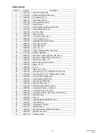
Страница 11: ... Main Burner Orifice 53 LP Gas 17 30299010 Gas Valve 3 1 2 WC VS820A 1039 Nat Gas 18 30299030 Gas Valve 10 WC VS820A 1120 LP Gas 19 42124000 Reflector Assembly pilot 20 40715000 Pilot Housing Assembly 21 40719000 End Flue Collar pilot end 22 40707000 Radiation Shield housing 23 40649000 Pilot Flue Baffle 24 40750000 Pilot Shield Assembly 25 40706000 Radiation Shield pilot 26 42184000 Pilot Tubing ...

Страница 12: ...y Item Number Refer to complete Model Number when ordering All replacement parts available when ordering MODEL NUMBER SUFFIXES N Natural Gas L Propane Gas 1 Self Generating Standing Pilot ALL ILLUSTRATIONS ARE INTENDED TO GIVE THE GENERAL IMPRESSION OF UNITS ONLY WE RESERVE THE RIGHT TO ALTER ANY SPECIFICATION WITHOUT NOTICE MODELS RSCA3 N5 L5 ...

Страница 13: ...t Gas 19 30333040 Gas Valve 10 WC VR8205A 2081 LP Gas 20 42125000 Reflector Assembly 21 42429000 End Flue Collar ignition end 21a 42468000 End Flue Collar ignition end with bleed tube hole LP Gas 22 30216000 Spark Electrode PSE GF2 23 03763000 Flame Sensor PSE GF3 24 30314070 Ignition Cable 7 25 30198040 Spark Ignition Module S87C 1030 26 42829000 Bracket Assembly Module Transformer 27 42830000 Br...

Страница 14: ...ed 18 30299020 Gas Valve 6 WC VS820A 1070 Nat Gas 19 30299030 Gas Valve 10 WC VS820A 1120 LP Gas 20 40720000 Reflector Assembly pilot 21 42431000 Pilot Housing Assembly 22 42425000 Radiation Shield housing 23 42421000 Pilot Flue Baffle 24 42424000 Pilot Shield 25 42434000 Pilot Tubing 26 40706000 Radiation Shield pilot 27 03462130 Pilot Generator System Nat Gas 28 03462140 Pilot Generator System L...

Страница 15: ... Nat Gas 16 03625450 Main Burner Orifice 45 LP Gas 17 41156000 Reverb Baffle Assembly 18 30333050 Gas Valve 6 WC VR8205A 2123 Nat Gas 19 30333040 Gas Valve 10 WC VR8205A 2081 LP Gas 20 41159000 Reflector Assembly 21 42429000 End Flue Collar ignition end 22 30216000 Spark Electrode PSE GF2 23 03763000 Flame Sensor PSE GF3 24 30314070 Ignition Cable 7 25 30198040 Spark Ignition Module S87C 1030 26 4...

Страница 16: ...ty 2 20 03625450 Main Burner Orifice 45 LP Gas Qty 2 21 30203000 Break Away Fitting 1 8 22 42042000 Bleed Tube Clamp Assembly 23 03333060 Nipple 1 2 x 2 24 03336080 Tee 1 2 25 03333020 Nipple 1 2 x Close 26 30333050 Gas Valve 6 WC VR8205A 2123 Nat Gas 27 30333040 Gas Valve 10 WC VR8205A 2081 LP Gas 28 42468000 End Flue Collar ignition end 29 30216000 Spark Electrode PSE GF2 30 03763000 Flame Senso...

Страница 17: ... 16 Form 43219000 Jan 09 1 3 4 2 7 28 29 30 41 43 38 42 39 40 44 14 23 24 25 33 34 35 26 27 11 12 19 20 22 21 17 16 15 18 5 32 31 36 32 31 10 8 9 11 12 37 33 34 35 19 20 6 ...

Страница 18: ...VE REMEDY The sole and exclusive remedy under this warranty is the replacement of the defective parts or heaters as hereinabove specified THE MANUFACTURER DOES HEREBY EXPRESSLY EXCLUDE ANY AND ALL LIABILITY FOR INCIDENTAL AND CONSEQUENTIAL DAMAGES UNDER THIS OR ANY OTHER WARRANTY Without intending to limit the aforesaid exclusion THE MANUFACTURER DOES HEREBY EXCLUDE ANY LIABILITY UNDER THIS OR ANY...

Отзывы: