16
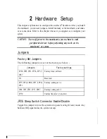
Hardware Setup
Multi I/O Port Addresses
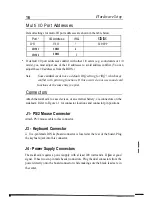
Default settings for multi-I/O port addresses are shown in the table below.
. .
Port* I/O Address IRQ
status
LPT1 378H 7 ECP/EPP
COM1 3F8H
4
COM2 2F8H
3
If default 1/0 port addresses conflict with other 1/0 cards (e.g. sound cards or 1/0
cards), you must adjust one of the 1/0 addresses to avoid address conflict. (You can
adjust these 1/0 addresses from the BIOS..)
Note:
Some
sound
cards have a default IRQ setting for IRQ 7, which may
conflict with printing functions. If this occurs do not use sound card
functions at the same time you print.
Connectors
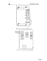
Attach the mainboard to case devices, or an external battery, via connectors on the
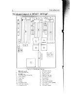
mainboard. Refer to Figure 1-1 for connector locations and connector pin positions.
J1 - PS/2 Mouse Connector
Attach PS/2 mouse cable to this connector.
J3 - Keyboard Connector
A
five-pin female DIN keyboard connector
the keyboard jack into this connector.
J4 - Power Supply Connectors
is located at the rear of the board. Plug
The mainboard requires a power supply with at least 200 watts and a
‘(
power good
signal. J3 has two six-pin male header connectors. Plug the dual connectors from the
power directly onto the board connector while making sure the black leads are in
the center,
.
Содержание 5SM2
Страница 1: ...j p l Pentium...


