background image

Quick Installation Guide

This Quick Installation Guide leaflet is designed for those people who are familiar with motherboard settings to set
up this new motherboard in order to boot up the system.  Refer back to the proper chapters if you have run in to
any problems.

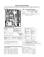
Diagram 1:  Motherboard Layout

USB1

1

#1

#2

#3

ISA SLOT

#1

#2

#3

PCI SLOT

A

GP POR

T

IDE1

IDE2

FDC

PR
T

COM2

COM1

SMC

37C669

3V

Lithium 

Battery

Flash BIOS

A

TX PWR

K/B

Conn.

PS/2

Conn.

#1

#2

SIMM SLOT

#1

#2

DIMM SLOT

TAG 16kx8

1
3
5

JP37

SW1

6

5

4

2 3

1

ON

P.B. SRAM

64Kx64

P.B. SRAM

64Kx64

EQ82C

6638AT

EQ82C6629

1
2
3

JP5

IR1

Socket 7

(for 586 CPUs)

SPK

RST

PW2

HDD 

LED

Turbo 

LED

J25

JP30

13579

1

1

JP4

JP12

+–

Power

LED

Keylock

*  If the board is 

5EHM (1M Cache)
then it should have

two P.B. SRAM.

(Optional)

1

1
2
3

JP44

A

T

 PWR

1
2
3

JP22

3

2

1

3

2

1

JP2

JP6

1

1
2
3

JP7

1
2
3

JP8

1
2
3

JP9

1 2 3

JP10

Table 1:  Memory Configurations

SIMM Bank DIMM Bank

DIMM 1 DIMM 2

RAM Type FPM/EDO FPM/EDO/

SDRAM

FPM/EDO/
SDRAM

Single RAM
Module Size (MB)

4/8/16/32 8/16/32/64/

128

8/16/32/64/128

Note: Do not install FPM or EDO SIMM/DIMM when you already

installed SDRAM type of DIMM.

Table 2:  Jumper Settings

CMOS clear: JP5 AT Power Supply Connector:  CN1 CPU Cooling Fan Connector:  JP12

Retain CMOS 1-2 please insert the AT power supply pin 1 2 3
data (default) plug into this header. function GND 12V NC

ATX Power Supply Connector:  P1 RST HD Led

Clear CMOS data 2-3 please insert the ATX power supply

plug into this header.

Connect the reset
button to this jumper

Connect the HDD led
to this jumper

USB1 PRT SPEAK Keylock

Plug the USB cable into this connector printer cable header Connect the cable Connect keyboard

IrDA (Infrared Devices Connector):  IR

Power Supply
Selection Jumpers:
JP2, JP6

of speakers to this
jumper

lock switch to this
jumper

pin 1 2 3 4 5 AT (default) 2Ð3 

Wake-On-LAN Header :  JP44

function Vcc Empty IRRX GND IRTX ATX 1Ð2 pin 1 2 3

DIMM Voltage:  JP37 Burst Mode:  JP22 Power Switch:  PW2 

function 5V END Sensor

3.3V DIMM
(default)

1Ð3 and  2Ð4 1Ð2 Intel, AMD Connect your power switch

to this jumper

TB Led PW Led

5V DIMM 3Ð5 and  4Ð6 2Ð3 Cyrix (momentary switch type) Connect the  Turbo

led to this  jumper

Connect the  power
led to this  jumper

Host Bus Frequency Selection Jumper:  JP7, JP8

JP7 JP8 CPU AGP PCI

2-3

(default)

open

(default)

66 66 33

1-2 2-3 100 66 33

SDRAM Frequency Selection Jumper:  JP9, JP10

JP9

2-3
(default)

SDRAM frequency is the same as CPU frequency
(60/66/75/83/100 MHz)

1-2 SDRAM frequency is the same as AGP frequency (66 MHz)

JP10

1-2
(default)

SDRAM is running at CPU frequency

2-3 SDRAM is running at AGP frequency

Jumper Settings for CPU Voltage & Frequency

V

oltage Settings:  JP30

Voltage 1Ð2 3Ð4 

5-6 

7Ð8 9Ð10 11Ð12

single 3.52V

close

open open open open 

close

singel 3.3V 

close

open open open 

close

open

dual 3.2V 

close

open open 

close

open open

dual 2.9V 

close

open 

close

open open open

dual 2.8V 

close

open open open open 

close

dual 2.2V open 

close

open open open open

CPU Frequency Settings:  SW1

Frequency 4 5 6 Multiplier 1 2 3

60 Mhz 

on 

off off 1.5/3.5x off off off

66 Mhz 

on 

off    off 

2.0x 

on 

off off

75 Mhz off 

on 

off 2.5x 

on on 

off

83 Mhz 

on on 

off 3.0x off 

on 

off

100 Mhz off off 

on 

4.0x 

on 

off 

on

4.5x 

on on on

Содержание 5eh5

Страница 1: ...5EH5 5EHM 586 CPU Supported PCI Mainboard User s Guide Technical Reference...

Страница 2: ...ise the manual or make changes in the specifications of the product described within it at any time without notice and without obligation to notify any person of such revision or change The informatio...

Страница 3: ...ttings Continued 10 AMD K5 K6 Series CPUs Setting 11 Cyrix 6x86 L MX Series CPUs Setting 12 Memory Configuration 13 Memory Configuration Table 13 Cache Configuration 13 Cache Size and RAM Locations 13...

Страница 4: ...22 Chipset Features Setup 25 Power Management Setup 27 PNP PCI Configuration Setup 30 Load Setup Defaults 32 Load BIOS Defaults 32 Integrated Peripherals 33 Supervisor Password 36 User Password 37 IDE...

Страница 5: ...e DRAM Controller Supports 2 strips of 72 pin FPM EDO 4 8 16 32MB SIMM symmetrical asymmetrical addressing Supports 2 strips of 168 pin FPM EDO SDRAM 8 16 32 64 128 MB 3 3V Unbuffered DIMM Memory conf...

Страница 6: ...amage to the board contact your dealer immediately Electrostatic Discharge Precautions Make sure you ground yourself before handling the mainboard or other system components Electrostatic discharge ca...

Страница 7: ...2 Connectors 2 EQ82C663X Chipset 13 Parallel Port Connector 3 Pipelined Burst SRAM 14 COM1 COM2 Connector 4 Super I O 15 ATX Power Connector 5 PnP FLASH BIOS 16 AT Power Connector 6 TAG SRAM 17 KB Con...

Страница 8: ...n PS 2 Conn 1 2 SIMM SLOT 1 2 DIMM SLOT TAG 16kx8 1 3 5 JP37 SW1 6 5 4 2 3 1 ON P B SRAM 64Kx64 P B SRAM 64Kx64 EQ82C 6638AT EQ82C6629 1 2 3 JP5 IR1 Socket 7 for 586 CPUs SPK RST PW2 HDD LED Turbo LED...

Страница 9: ...s before performing any work on the mainboard or system Jumpers This mainboard uses different colors of jumper caps to identify different functions of the jumpers Jumper Cap Color White Black Blue Red...

Страница 10: ...burst mode 1 Press Delete key to enter the BIOS setup menu during the boot up 2 Select Chipset Features Setup 3 Set the Linear Burst to Enabled 4 Press Esc to go back to the main menu and choose Save...

Страница 11: ...in the market 3 3V and 5V and most of SDRAM DIMMS are 3 3V Choose the correct voltage according to the DIMM that you are using DIMM Voltage JP37 Setting 3 3V default 2 4 6 1 3 5 5V 2 4 6 1 3 5 Cautio...

Страница 12: ...using a AGP card 2 Use 8ns SDRAM or faster for PC100 when using a host bus frequency of 100MHz However this limitation does not apply to EDO modules 3 When the SDRAM module is slower than 8ns JP9 and...

Страница 13: ...l The CPUs which fall under the single voltage category are P54C AMD K5 and Cyrix 6x86 The CPUs which fall under the dual voltage category are P55C AMD K6 and Cyrix 6x86L MX This board is designed to...

Страница 14: ...U Frequency Setting SW1 Voltage Setting JP30 External 60MHz Ratio 3 0x P55C 180MHz MMX External 66MHz Ratio 3 0x P55C 200MHz MMX External 66MHz Ratio 3 5x P55C 233MHz MMX DualVoltage 2 8V default 1 2...

Страница 15: ...Ratio 3 0x Dual Voltage 2 9V Dual Voltage 2 2V Dual Voltage 3 2V 1 2 3 4 5 6 ON 1 2 3 4 5 6 ON 1 2 3 4 5 6 ON 1 2 3 4 5 6 ON 1 2 3 4 5 6 ON 1 2 3 4 5 6 ON 1 2 3 4 5 6 ON 1 2 3 4 5 6 ON External 66MHz...

Страница 16: ...1 2 3 4 5 6 ON Cyrix 6x86MX PR200 External 75MHz Ratio 2 0x 1 2 3 4 5 6 ON 1 2 3 4 5 6 ON 1 2 3 4 5 6 ON Cyrix 6x86MX PR266 External 83MHz Ratio 2 5x 1 2 3 4 5 6 ON Dual Voltage 2 9V 1 3 5 7 9 11 JP3...

Страница 17: ...to complete a bank Memory Configuration Table DIMM Bank SIMM Bank DIMM 1 DIMM 2 RAM Type FPM EDO FPM EDO SDRAM FPM EDO SDRAM Single RAM Module Size MB 4 8 16 32 8 16 32 64 128 8 16 32 64 128 Note Do...

Страница 18: ...sound cards have a default IRQ setting for IRQ7 which may conflict with printing functions If this occurs do not use sound card functions at the same time you print Connectors Attach the mainboard to...

Страница 19: ...ystem SPEAKER PC Speaker Connector Attach a 4 pin PC speaker cable from the case to this connector TB LED Turbo LED Connector Attach a 2 pin turbo LED cable to it The LED lights when the system is in...

Страница 20: ...computer through the LAN card The cable should be included with the LAN card JP44 Pin Assignment 5V GND SENSOR 1 2 3 PS1 PS 2 Mouse Connector Attach 6 pin male PS 2 mouse cable to this connector to e...

Страница 21: ...ctly onto the board connector while making sure the black leads are in the center IDE1 IDE2 Primary Secondary IDE Device Connectors Attach the IDE device cables to these connectors ATX PWR P1 ATX Powe...

Страница 22: ...fan will stop when the system is into the suspend mode if you enable the Suspend Mode in the BIOS setup CPU Cooling Fan Pin Assignment NC 12V GND 3 2 1 IR Infrared Device Connector Attach a 5 pin inf...

Страница 23: ...ONFIGURATION LOAD SETUP DEFAULTS LOAD BIOS DEFAULTS INTEGRATED PERIPHERALS SUPERVISOR PASSWORD USER PASSWORD IDE HDD AUTO DETECTION SAVE EXIT SETUP EXIT WITHOUT SAVING Time Date Hard Disk Type Esc Qui...

Страница 24: ...Help Shift F2 Change Color F3 Toggle Calendar Base Memory 640K Extended Memory 31744K Other Memory 384K Total Memory 32768K 2 Use arrow keys to move between items and select values Modify selected fi...

Страница 25: ...B 3 1 2 in or None Floppy 3 Mode Support Choose Disabled default or Enabled When enables this function the system will support 720KB 1 25MB 1 44MB 3 different mode floppy diskette Note This function i...

Страница 26: ...abled C8000 CBFFF Shadow Disabled CC000 CFFFF Shadow Disabled D0000 D3FFF Shadow Disabled D4000 D7FFF Shadow Disabled D8000 DBFFF Shadow Disabled DC000 DFFFF Shadow Disabled 2 Use the arrow keys to mo...

Страница 27: ...drive B to drive B and drive A The Default setting is Disabled Boot Up Num Lock Status Choose On default or Off On puts numeric keypad in Num Lock mode at boot up Off puts this keypad in arrow key mod...

Страница 28: ...nitor may be incorrect if uses with MPEG card Enable this option to make the monitor normal Disabled Disable Snoop function default OS Select for DRAM 64MB OS2 Choosing this when you are using OS 2 op...

Страница 29: ...1 DRAM Timing 60ns Bank 2 3 DRAM Timing 60ns Bank 4 5 DRAM Timing 60ns DRAM Read Pipeline Enabled Tag Config dirty bit 1 Cache Rd CPU Wt Pipeline Enabled Linear Burst Disabled Video BIOS Cacheable Ena...

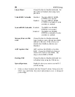
Страница 30: ...ole At 15M 16M Choose Enabled or Disabled default Some interface cards will map their ROM address to this area If this occurs you should select Enabled otherwise use Disabled AGP Aperture Size AGP cou...

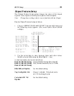
Страница 31: ...F5 Old Values Shift F2 Color F6 Load BIOS Defaults F7 Load Setup Defaults Primary INTR ON IRQ3 COM 2 Primary IRQ4 COM 1 Primary IRQ5 LPT 2 Primary IRQ6 Floppy Disk Primary IRQ7 LPT 1 Primary IRQ8 RTC...

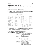
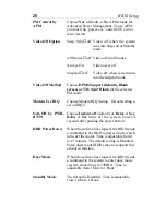
Страница 32: ...hoose Modem IRQ Setting Default setting is set on IRQ3 Soft Off by PWR BTTN Choose Instant off default or Delay 4 Sec Delay 4 Sec turns off the system power 4 seconds after pushing the power button HD...

Страница 33: ...fault or On If you choose the system Off will not monitor the signal of DMA master and when you choose On the system will not have SMI signal until the master is finished while the master is working M...

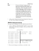
Страница 34: ...rom the Main Menu and the following screen appears The screen below shows default settings ROM PCI ISA BIOS PNP PCI CONFIGURATION AWARD SOFTWARE INC Resources Controlled By Manual Reset Configuration...

Страница 35: ...igned to Choose PCI ISA PnP or Legacy ISA If the first item is set to Manual you could choose IRQX and DMAX assigned to PCI ISA PnP card or ISA card CPU to PCI Write Buffer Choose Enabled default or D...

Страница 36: ...mmended if you need to reset the system setup Note The SETUP Defaults are optimized for the most stabilized performance Load BIOS Defaults Choose this item and the following message appears Load BIOS...

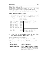
Страница 37: ...nabled OnChip IDE Second Channel Enabled IDE Prefetch Mode Enabled IDE HDD Block Mode Enabled IDE Primary Master PIO Auto IDE Primary Slave PIO Auto IDE Secondary Master PIO Auto IDE Secondary Slave P...

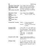
Страница 38: ...o Supports Ultra DMA mode Onboard FDC Controller Enabled Use the on board floppy controller default Disabled Turn off the on board floppy controller Onboard UART 1 Onboard UART 2 Choose UART 1 2 s I O...

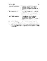
Страница 39: ...ECP The mode depends on your external device that connects to this port ECP Mode Use DMA Choose DMA3 default or DMA1 This setting only works when the Onboard Printer Mode is set at the ECP mode Parall...

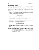
Страница 40: ...owing message appears Enter Password 2 Enter a password and press Enter If you do not wish to use the password function you can just press Enter and a Password disabled message appears 3 After you ent...

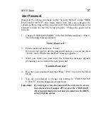
Страница 41: ...d and press Enter If you do not wish to use the password function you can just press Enter and a Password disabled message appears 3 After you enter your password the following message appears prompti...

Страница 42: ...dingly Note This function is only valid for IDE hard disks ROM PCI ISA BIOS CMOS SETUP UTILITY AWARD SOFTWARE INC Do you accept this drive C Y N N ESC Skip HARD DISKS TYPE SIZE CYLS HEAD PRECOMP LANDZ...

Страница 43: ...er Connect the HDD led to this jumper USB1 PRT SPEAK Keylock Plug the USB cable into this connector printer cable header Connect the cable Connect keyboard IrDA Infrared Devices Connector IR Power Sup...

Страница 44: ...l versions with different Cyrix 6x86 P166 66MHz 2 0x on off off off off off voltages Please ask your dealer for the correct voltage Cyrix 6x86 P200 75MHz 2 0x on off off off on off 2 3 open 2 3 1 2 Cy...

Отзывы: