background image

SOUTHWEST WINDPOWER 

April 2006 

20 

Whisper 500 Battery Charging Manual 

Document #0023 Rev C 

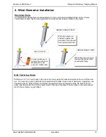
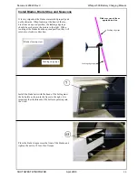
It is very important the blades are installed properly and 
not backwards.  When looking at the front of the tur-
bine from an 

upwind

 position, the leading edge tape 

should be as shown in the picture to the right.  When 
looking at the blades from an 

upwind 

position, they will 

rotate in a clockwise direction.   


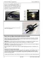
Install the blade bolts with the head of the bolt against 
the hub plate as shown in the figure to the right.  It is 
important that the threads of the bolts are pointing into 
the wind.   


Place the blade straps across the front of the blades, and 
tighten the nuts to 18 foot-lbs of torque.   

Leading edge tape 

Blade close-up view 

Blades as viewed from 

upwind direction


Leading edge tape


Leading edge tape


13 

Install Blades, Blade Strap and Nosecone   

Содержание 30 FOOT (9 Meter) TOWER KIT for WHISPER 500

Страница 1: ...ications Southwest Windpower Inc 1801 W Route 66 Flagstaff Arizona 86001 Phone 928 779 9463 Fax 928 779 1485 Email info windenergy com Web page http www windenergy com 1 April 2006 Southwest Windpower...

Страница 2: ...mounting mast tower well away from occupied buildings and power lines a minimum of 100m 300 ft is recommended STOP DANGER If the generator appears or sounds loose in the tower or is making an unusual...

Страница 3: ...ator Wiring 8 Brake Switch 10 Diversion Load Wiring and Configuration 11 Transformer 11 4 Wind Generator Installation 13 Electrical Tests 13 Install Tower Insert 14 Install Tail Fin 17 Install Tail Bo...

Страница 4: ...400 amp hours of capacity and a 24 volt Whisper 500 should have a battery bank with a minimum of 800 amp hours of capacity Tower The Whisper 500 Wind Generator is designed to fit on a 5 inch schedule...

Страница 5: ...roller Diversion Load Battery Bank Transformer HVLV only External Brake Switch Optional Extra External Brake Switch Whisper 500 Wind Generator Fuse Note Size the DC wire between the Whisper Controller...

Страница 6: ...is mounting position is necessary to provide adequate cooling for the electronics and rectifier heat sink The 4600 Diversion Load MUST be mounted against a wall to provide adequate heat transfer The c...

Страница 7: ...he controller to the batteries Use caution when connecting the battery leads to avoid shorting them together Correct polarity MUST be observed when connecting the battery cables Depending on your syst...

Страница 8: ...enerator is determined by the power produced by the generator system voltage and the distance between the generator and controller Distances are one way and should include the height of the tower Refe...

Страница 9: ...77 554 2 0 288 577 1154 2 0 88 176 352 703 3 0 363 726 1452 3 0 111 221 442 885 4 0 459 918 1837 4 0 140 280 560 1120 Distance Feet Distance Meters Note The Whisper 500 High Voltage cannot be wired di...

Страница 10: ...he switch up is brake on and moving it down is normal operation Use three 6 AWG wires to connect a wire in parallel with each of the three phases from the Whisper Controller The three wires are connec...

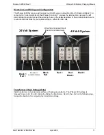
Страница 11: ...ires as shown in the below depictions of the terminal block Be sure to wire the terminal block for your system voltage either 24 or 48 volts Transformer High Voltage Only Install transformer on heat r...

Страница 12: ...x2 x4 x2 x4 A B C x1 x2 x3 x4 x1 x2 x3 x4 x1 x2 x3 x4 A B C x1 x2 x3 x4 x1 x2 x3 x4 x1 x2 x3 x4 A B C x1 x2 x3 x4 x1 x2 x3 x4 x1 x2 x3 x4 A B C x1 x2 x3 x4 x1 x2 x3 x4 x1 x2 x3 x4 To Blue Wires of Co...

Страница 13: ...emplate at the end of this man ual You must use a sharp drill bit and a powerful drill to make these holes in steel pipe Applying a cut ting fluid at the tip of the drill bit can improve the performan...

Страница 14: ...of 1 5mm 1 16in play is allowed Tower Pipe or tube must be tight against insert when the mount ing bolts are tightened B Install the tower insert onto the yaw shaft Place the three M10x55 screws into...

Страница 15: ...on the yaw shaft C Install the turbine without the blades onto to the tower top Be careful not to pinch or short any of the wires Rotate the tower insert so the six holes in the tower match the corre...

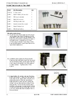
Страница 16: ...l fin to tail boom Tail strap to tail fin 3 IAR52 M8x24 nylon flatwasher 2 Nose cone 4 IAR07 M8x20 SS hex screw 2 Nose cone 5 IAR35 M8x30 SS bolt 7 Tail fin to tail boom Tail boom to lower weldment 6...

Страница 17: ...he tail boom with a ny lon washer sandwiched between the metal tabs on the tail boom and the tail fin Repeat so the fin is secured with three bolts B Repeat the above step for the second fin but use o...

Страница 18: ...d on the outside of the tail strap A nylon washer is sandwiched between the tail strap and tail fin At this point only finger tighten the nylock nut E Then place the bolt in the side of the strap with...

Страница 19: ...nd a sledgehammer Insert the tail boom into the lower weldment until the hole in the lower weldment matches the through hole in the tail boom If the holes are nearly lined up but not perfect then you...

Страница 20: ...he blades from an upwind position they will rotate in a clockwise direction Install the blade bolts with the head of the bolt against the hub plate as shown in the figure to the right It is important...

Страница 21: ...attery is not connected to the controller Never operate the Whisper 500 without the battery properly connected to the Whisper Controller IMPORTANT The battery bank must have some charge on it for the...

Страница 22: ...ecting a battery cable from the Whisper Controller Note that if voltage regulation points are set using the Optional Display they will be lost if the Reset Switch is depressed or a battery cable is di...

Страница 23: ...set points set using the Optional Display In other words it is not additive with the Optional Display set points It is not neces sary to depress the Reset Switch after changing the switch setting Swi...

Страница 24: ...e display may be located up to 300 meters 1000 feet from the Whisper Controller Use Category 5 ethernet cable The cable with connectors may be purchased at electronics supply stores Install the displa...

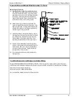
Страница 25: ...ires The terminal block connections are labeled and the polarity should be observed since some anemometers require spe cific polarity connections A ground shield if applicable should be connected to t...

Страница 26: ...certain system parameters i e battery voltage and turbine state i e whether power is being generated The LCD Display is an interface to the many operational parameters and system measurements of which...

Страница 27: ...sion Load is called the Regulation On Voltage This point may be altered by adjusting the potentiometer on the controller s circuit board See Section 5 on the Whisper Controller PCB The table below pre...

Страница 28: ...at the factory for room temperature operation however de viations from room temperature can cause the LCD to appear too dark or too light Carefully insert a screw driver through the display lid and t...

Страница 29: ...he turbine is diverted to the dumpload by the controller The OFF mode will brake the turbine and prevent it from turning in light winds The Controller can switch to OFF Stop mode in any of the followi...

Страница 30: ...p B go to reset menu A reset readings Reset Menu Reset Page A RESET B CANCEL B return to reset menu B Ring Mode On A batteries charging A OFF_REM B SKIP B go to regulation set menu Mode Off A batterie...

Страница 31: ...ng Manual Document 0023 Rev C April 2006 Energy A History Main Display Mode Regulation Regulation On Regulation Off A A B B B A A A Reset B B Reset B B Charge On Off A A B B B B Increase Set Point Inc...

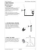
Страница 32: ...tempting to stop the turbine in high winds can damage the alternator 3 INSPECT THE TOWER Follow all inspection and maintenance requirements of the tower manufacturer Tighten all nuts and bolts especia...

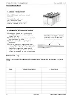
Страница 33: ...e parts B Check tightness of all tower mounting nuts and bolts and propeller mounting bolts C Check all bearings Just perceptible play is acceptable D Clean the propeller with mild scrubbing agent to...

Страница 34: ...April 2006 SOUTHWEST WINDPOWER 34 Document 0023 Rev C Whisper 500 Battery Charging Manual Date Problem Observation Action Taken...

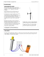
Страница 35: ...place the diode b Wind generator still does not start On a day of moderate wind disconnect any two wires If the wind generator starts the problem is in the Whisper Controller and contact Southwest Win...

Страница 36: ...bration i Clean with soap or bug cleaner i Refinish prop and replace tape i Replace or repair propeller i See blade installation i Turn blades over Leading edge advances clockwise from upwind view i B...

Страница 37: ...tween generator and Whisper Controller c Whisper Controller diodes open or wire is disconnected at diode terminal a Battery voltage over 50 high b Incorrect generator connection a Disconnected wire be...

Страница 38: ...he wind generator connection voltage see figures below 2 Change the transformer voltage HVLV models only see next page 3 Change the Whisper Controller voltage see Whisper Controller Owners Manual 4 Ch...

Страница 39: ...ts to ground Clean with mineral spirits and sand lightly to remove pitting or fretting Yaw bearings should be smooth with just perceptible play Brushes are copper graphite pads soldered to a beryllium...

Страница 40: ...ely 2 Weigh each blade separately use a grocery store scale and mark weight on each blade 3 Cut one or two sheet lead weights equal to the difference in weight between the heaviest and the other blade...

Страница 41: ...13 Retaining Ring 72mm Internal 1 15 Bearing 6206 2RS 2 16 17 Bearing 6207 2RS 4 18 Nylock Nut 7 8 14 1 19 Bolt 7 8 14 x 4 3 4 1 20 Cord Grip 3 4NPT 2 21 Lock Washer M5 SS 2 22 Screw M5 x 16 SS 4 23 S...

Страница 42: ...April 2006 SOUTHWEST WINDPOWER 42 Document 0023 Rev C Whisper 500 Battery Charging Manual Whisper 175 Exploded View Whisper 175 Vista desagregada...

Страница 43: ......

Страница 44: ......

Отзывы: