


SBI/SBN Vertical Multistage Centrifugal Pumps
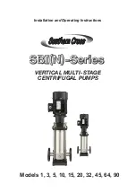
Min.Q (%)
30
20
10
0
40 60 80 100 120 140 t (°C)
2
4.3 Minimum inlet pressure-NPSH
To avoid cavitation, make sure that there is a minimum pressure on the suction side of the pump.
NPSH
A
:
Net Positive Suction Head Available
— The net positive suction head available is a function of the
pump suction system.
NPSH
R
:
Net Positive Suction Head Required
— The net positive suction head required is a function of the pump
design at the operating point on the pump performance curve.
NPSH
A
=Ha-Hs-Hf-Hv-Hst (in meters head)
Ha:
Barometric pressure.(That can be set to 10.2 m.)
Hs:
Suction lift.
Hf:
Friction loss in suction pipe.
Hv = K
T
+K
H
:
Vapor pressure
K
T
:
Pressure reduction due to liquid temperature.
K
H
:
Pressure reduction due to elevation above sea level.
If the liquid is water, refer to the table below to determine the
values of
K
T
and
K
H.
T (°C )
20
30
40
50
60
70
80
90
100
110
120
K
T
(m)
0.2
0.4
0.8
1.3
2.2
3.3
5
7.4
11
15
22
H (m)
0
500
1,000 1,500 2,000 2,500 3,000
K
H
(m)
0
0.55
1.1
1.65
2.2
2.75
3.3
Hst:
Safety margin. (minimum: 0.5 meters head)
NPSH
A
>
NPSH
R
:
Pump running will be fine.
NPSH
A
<
NPSH
R
:
The pump will be dry running or cavitating.
WARNING:
Stop operation of the pump if cavitation occurs. Cavitation will cause pump damage and the resultant damage is not subject to
warranty
4.4 Minimum nominal flow rate
To prevent overheating of the internal pump components, the pump should not be used at flows below the minimum flow rate.
WARNING:
Do not run the pump against a closed discharge valve for longer than a few seconds.
The curve below shows the minimum flow rate required as a percentage of the pump nominal flow rate in relation to the liquid temperature.
4.6 Electrical data
See the motor nameplate.
WARNING:
Make sure that the supply voltages, phase and frequencies correspond to the motor specifications.
4.7 Number of starts per hour
Motors up to and including 4 kW: Maximum 100 starts per hour.
Motors of 5.5 kW and up: Maximum 40 starts per hour.
.
WARNING:
If you use another brand of motor then check the manufacturer’s instructions for the maximum frequency of starts.
5. Installation
Always refer to the local or national regulations and codes relating to the selection of the installation site, the water
and power connections, etc.
5.1 Position
Pumps should be installed in a protected environment – not exposed to weather. Make sure that there are no
obstructions to prevent proper motor cooling.
5.2 Anchoring
The pump must be secured to a solid foundation by bolts through the holes in the flange or base plate.
An illustration of page 7 shows the bolt location and the pipe connections.


