SC8913 EVM USER GUIDE
SOUTHCHIP SEMICONDUCTOR
SOUTHCHIP CONFIDENTIAL
Copyright © 2018, Southchip Semiconductor Technology (Shanghai) Co., Ltd
14
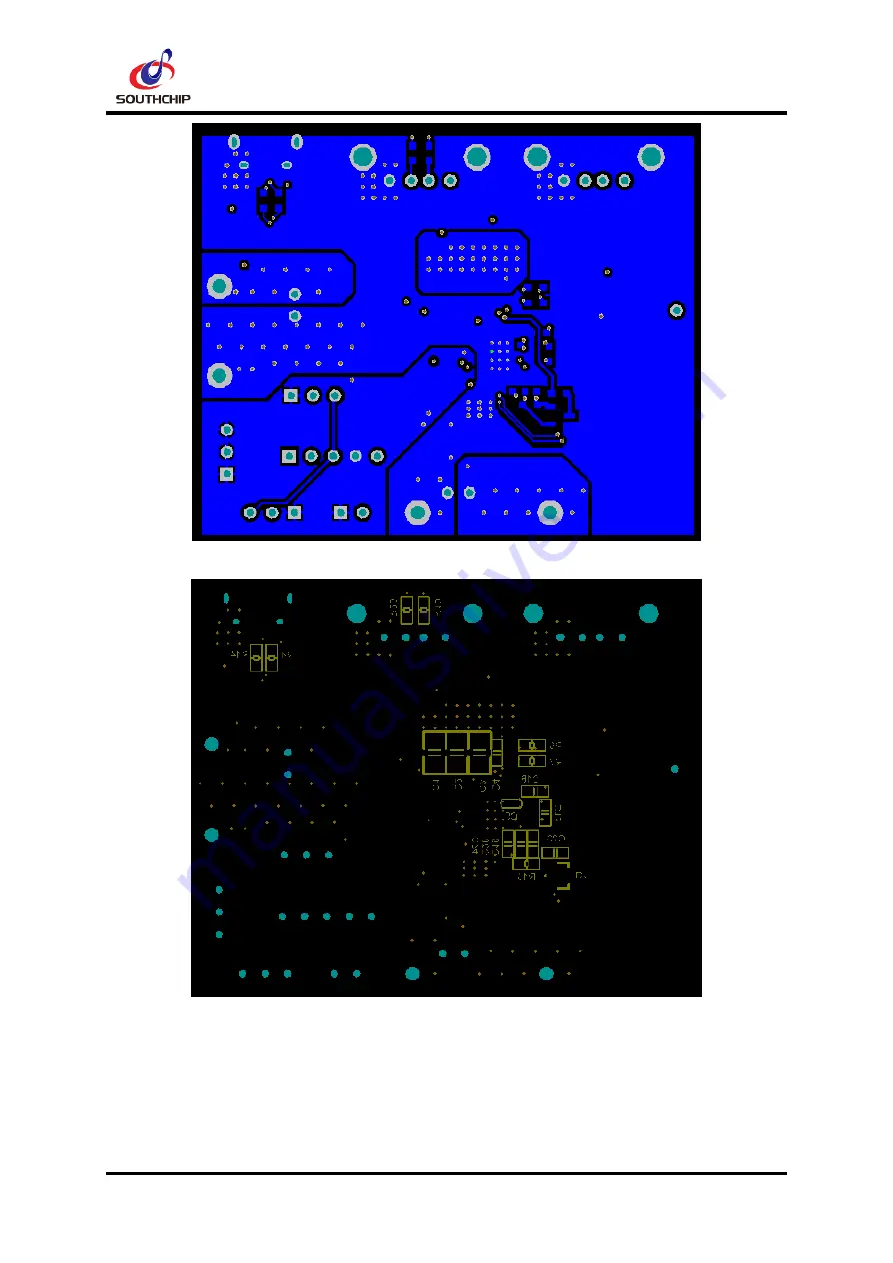
Figure 8 Bottom Layer
Figure 9 Bottom Silkscreen
Страница 1: ...SC8913 EVM USER GUIDE Southchip Semiconductor...
Страница 2: ...FET Yes Support I2C interface Yes Support power path management Yes Smart detection function Yes ADC resolution 10 bits VBUS operation range in charging mode VBAT 25V support up to maximum 26V VBAT op...
Страница 3: ...ed by external power if I2C tool is connected with computer the power will be provided by computer AGND is analog ground INT is interrupt signal P4 ADIN ADIN lies on the right pin of P4 ADIN is analog...
Страница 4: ...VBUS is decided by external configuration the Rup and Rdown values marked with red color on the lower part of the interface should be filled according to the actual resistance on EVM In this way the v...
Страница 5: ...y impendence compensation function no matter internal or external configuration Reg 0x00 7 6 IRCOMP is used to set compensation voltage So the real target voltage can be calculated as follow VBAT_cmp...
Страница 6: ...ence voltage can be calculated as follow VBUSREF_I 4 x VBUSREF_I_SET VBUSREF_I_SET2 1 x 2 mV The recommended VBUS voltage range is from 3 5V to 25 6V When VBUS is lower than 10 24V it is suggested to...
Страница 7: ...tor value IBUS_LIM A IBUS_LIM_SET 1 256 IBUS_RATIO 10 m RS1 RS1 value is 10m the default IBUS current limit is 3A 1 1 5 IBAT Current Limit setting IBAT current limit function is effective in both char...
Страница 8: ...FB_VALUE set by Reg0x0F 7 0 VBAT_FB_VALUE2 set by Reg0x10 7 6 When Reg 0x08 1 VBAT_MON_RATIO 0 VBAT_MON_RATIO 12 5 default When Reg 0x08 1 VBAT_MON_RATIO 1 VBAT_MON_RATIO 5 For 1 2 cell application it...
Страница 9: ...nterrupt bit and INT pin will assert interrupt signal Specification description can be referred to SC8913 datasheet 1 2 5 Dithering function test configuration If switching frequency dithering functio...
Страница 10: ...10 100nF 100nF 25V GRM188R61E104KA01 Murata 5 C5 Capacitor X5R 0402 25V 10 100nF 100nF 25V GRM155R61E104KA87 Murata 1 C6 C7 POSCAP Solid electrolytic capacitor 6 3x11 25V 100uF 100uF 25V std std 2 C8...
Страница 11: ...td std 1 P5 P6 P7 Header 3 Pin Header 3 std std 3 Q1 Q2 Q4 30V PMOS SOT23 55mohm 4 3A 30V 4 3A AO3401A AO3401 VS3407 A CJ3401A A O 3 Q3 NPN NMOS SOT23 2N7002 MMBT3904 NXP 1 R1 Metal resistor 1206 1W 1...
Страница 12: ...UIDE SOUTHCHIP SEMICONDUCTOR SOUTHCHIP CONFIDENTIAL Copyright 2018 Southchip Semiconductor Technology Shanghai Co Ltd 12 4 PCB Layout SC8913 EVM board PCB layout is as follow Figure 4 Top Silkscreen F...
Страница 13: ...SC8913 EVM USER GUIDE SOUTHCHIP SEMICONDUCTOR SOUTHCHIP CONFIDENTIAL Copyright 2018 Southchip Semiconductor Technology Shanghai Co Ltd 13 Figure 6 Mid Layer1 Figure 7 Mid Layer2...
Страница 14: ...SC8913 EVM USER GUIDE SOUTHCHIP SEMICONDUCTOR SOUTHCHIP CONFIDENTIAL Copyright 2018 Southchip Semiconductor Technology Shanghai Co Ltd 14 Figure 8 Bottom Layer Figure 9 Bottom Silkscreen...
Страница 15: ...p Semiconductor Technology Shanghai Co Ltd 15 5 Tested Data and Waveform 5 1 VBUS Output Voltage Ripple in Discharging Mode fsw 300kHz L 2 2uH RS1 10mR RS2 5mR COMP 10k 22nF VBAT 3 6V VBUS 5V IBUS 0A...
Страница 16: ...ging Mode fsw 300kHz L 2 2uH RS1 10mR RS2 5mR COMP 10k 22nF Loop bit 1 VBAT 3 6V VBUS 5V IBUS 0A 3A Slew Rate 1A uS VBUS 9V IBUS 0A 2A Slew Rate 1A uS VBUS 12V IBUS 0A 1 5A Slew Rate 1A uS 5 3 VBUS Vo...
Страница 17: ...nology Shanghai Co Ltd 17 IBUS 0A VBUS 5 12V Slew Rate 8mV uS IBUS 0A VBUS 12 5V Slew Rate 8mV uS 5 4 Current Limit Accuracy in Charging Discharging mode fsw 300kHz L 2 2uH RS1 10mR RS2 5mR COMP 10k 2...
Страница 18: ...AT 4 2V VBUS 5V 9V 12V VBAT 3 6V VBUS 5V 9V 12V VBAT 3 0V VBUS 5V 9V 12V 5 6 Supply Current fsw 300kHz L 2 2uH RS1 10mR RS2 5mR COMP 10k 22nF VBAT 3 6V Test Condition Test Result PSTOP 3 3V VBUS float...
Страница 19: ...ging Mode fsw 300kHz L 2 2uH RS1 10mR RS2 5mR COMP 10k 22nF VBAT 3 6V Test Condition Test Result VBUS 5V IBUS 3A Temperature rise of IC surface T_RISE 13 C VBUS 9V IBUS 2A Temperature rise of IC surfa...
Страница 20: ..._LIM 2A EOC_SET 0 IBUS_EOC 0 231A 11 5 IBUS_LIM Recharge voltage threshold VBUS 12V Set VBAT_TARGET 4 2V VBAT_RECHRG 4 01V 95 5 VBAT_TARGET Battery over voltage threshold VBUS 5V Set VBAT_TARGET 4 2V...