background image

Soundcraft Vi1™ User Guide Issue 0610

Page 8 - 2

There are five User Defined pages User 1, 2, 3, 4 and 5 that can be created, and each of these can  
contain any combination of the channels that appear on the three Fixed layers. It is also possible to  
arrange VCA Master faders within the User-defined Fader pages, along side input channels. There are no 
restrictions on how many times you can use a particular channel, so for example it is possible to assign a 
vocal channel to the same fader in all five User Pages, meaning that it will appear to remain in the same 
place on the surface regardless of which User Page is selected. 

To configure a User layer

Press the Setup button in the Input Fader Page control section.
This opens up a setup screen across the Vistonics screens.

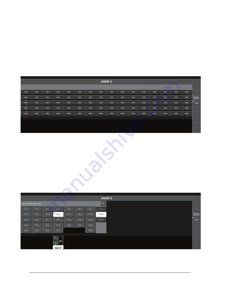
Each Setup screen contains five rows of buttons, corresponding to the User Pages 1, 2, 3, 4 and 5 for the 
16 fader strips. If you load a Default Show, all of the faders in all of the layers will have a default setting of 
NONE, which means that no channels are yet assigned to any of the faders in the User Pages.

To start assigning channels to the fader Strips, touch any of the buttons labeled ‘NONE’ in the previous 
screenshot, corresponding to the position and layer of the fader you want to assign something to. Normally 
you would start at the top left and work across each layer, assigning the faders in order.

Touching any of the ‘NONE’ buttons opens up the ‘Channel Select’ screen that then allows you to choose 
any of the input channels on the desk to be assigned to your chosen fader.

The tabs on the right side of the screen allow all available input channels or the VCA Masters to be  
accessed.

Содержание Vi1

Страница 1: ...Soundcraft Vi1 User Guide Issue 0610 i User Guide...

Страница 2: ...9 Warning Any modification or changes made to this device unless explicitly approved by Harman will invalidate the authorisation of this device Operation of an unauthorised device is prohibited under...

Страница 3: ...HARDWARE OVERVIEW 2 2 THE CONSOLE REAR CONNECTORS 2 3 Mains Power Supply Inlet 2 3 Audio And Data Rearcon 2 3 OPTIONAL STAGE BOX 2 5 Stage Box Description 2 5 Card Function Overview 2 5 Redundant MAD...

Страница 4: ...GURATION 4 6 Pairing of input channels 4 6 Pair An input Channel 4 6 EQUALISER 4 7 General 4 7 Equaliser Band Highlight 4 8 BAND Field 4 8 SHELF Switch 4 8 EQUALISER Field 4 8 DYNAMICS 4 9 General 4 9...

Страница 5: ...DYNAMIC 5 9 PAN 5 10 LOW CUT Field 5 10 PHASE Field 5 10 DLY Field 5 10 MATRIX 6 1 SIGNAL FLOW 6 1 FUNCTION 6 1 Adjusting A Matrix Send Level 6 2 MATRIX CONFIGURATION 6 2 SOURCE field 6 2 MTX Point F...

Страница 6: ...to an OUTPUT 10 5 INSERT 10 6 Patching An Insert Point To An Input Channel 10 6 Patching Insert Send Or Return Signals To The Connectors Or MADI Channels 10 6 Stereo Inserts 10 6 DIRECT OUT 10 7 KEY...

Страница 7: ...us Master Meters 13 2 Master Output Meters 13 2 Monitor Meters 13 2 Scale 13 2 Meters On The Master Section Screen 13 3 Touch Selection 13 3 Peak Hold 13 4 Ballistics 13 4 MAIN MENU 14 1 MAIN 14 1 SEC...

Страница 8: ...ist Open 15 19 CUE LIST PAGE GPIO Misc Field Touched 15 20 Global Filter 15 21 ISO Key Functionality 15 21 Press Hold ISO Key Functionality 15 21 Global Filter ON OFF switch 15 21 Edit Global Filter M...

Страница 9: ...COPYING FX PARAMETERS 18 4 LIBRARIES 18 6 NAVIGATING AND MANAGING LIBRARIES 18 8 COPY TO LIBRARY 18 9 PASTE FROM LIBRARY 18 10 EXPORTING AND IMPORTING LIBRARIES 18 11 SOUNDCRAFT Vi1 FEATURES AND SPEC...

Страница 10: ...c Equalisers 20 19 MIDI 21 1 Main Menu MIDI page open RX Channel list selected 21 1 DEVICE LISTS 21 1 Main Menu MIDI page open TX Channel list selected 21 3 Main Menu MIDI page open Transmit Device ID...

Страница 11: ...Soundcraft Vi1 User Guide Issue 0810 Page 1 1...

Страница 12: ...battery pack or batteries installed shall not be exposed to excessive heat such as sunshine fire or the like This apparatus may not be used as a Television set Use only with the cart stand tripod brac...

Страница 13: ...ning flammable gases or chemicals THIS APPARATUS MUST BE EARTHED Under no circumstances should the safety earth be disconnected from the mains lead The mains supply disconnect device is the mains plug...

Страница 14: ...he prod uct s enclosure that may be of sufficient magnitude to constitute a risk of electric shock to persons CAUTIONS The exclamation point within an equilateral triangle is intended to alert the use...

Страница 15: ...age fluctuations immediately switch off the mixer and unplug from the mains Signal Levels It is important to supply the correct input levels to the console otherwise signal to noise ratio or distortio...

Страница 16: ...0 5 110 0 25 115 Conforming to this directive will minimise the risk of hearing damage caused by long listening periods A simple rule to follow is the longer you listen the lower the average volume s...

Страница 17: ...lst in transit both to and from the Dealer or Soundcraft and postage must be prepaid 4 This warranty shall only be available if a the Equipment has been properly installed in accordance with instructi...

Страница 18: ...see below Busses 24 Grp Aux Matrix plus main LCR Mix and LR Solo busses a maximum of 8 matrix outputs can be configured I O Capability The following I O is available and can be patched to any channel...

Страница 19: ...Lexicon Multi FX processors x8 with FX Card Control Surface Inputs 16 input faders switchable in 4 fixed and 5 configurable layers to access 64 inputs Widescreen Vistonics channel strip interface x c...

Страница 20: ...Outputs plus snapshot Cue List and diagnostics info display Misc Gang mode for temporary linking of any number of channels or outputs for quick adjustment and setup Controls for Mute Group and VCA Gr...

Страница 21: ...ection contains 16 complete Fader strips with full state overview The Master bay contains 8 Output Fader strips the Masters and 16 Output encoders that give a total of 27 Output levels that can be dir...

Страница 22: ...able to control up to 64 inputs and 27 mix busses via its 16 input strips 8 bus master strips and the LCR masters To do this the console has a number of layers which the user accesses via the layer co...

Страница 23: ...Input channel related controls The Channel encoders are assigned with Input channel related functions The output encoders are normally used as Output faders and are also context sensitive There are f...

Страница 24: ...e Monitoring system contains the functionality to listen to and monitor the audio signal at several points in the console TB OSC system contains the Talkback functionality and the oscillator settings...

Страница 25: ...functions Snapshot allows the console s automated settings to be saved and recalled Menu opens the Menu page where central configurations can be done Copy paste functionality can be used in different...

Страница 26: ...Soundcraft Vi1 User Guide Issue 0810 Page 1 16...

Страница 27: ...Soundcraft Vi1 User Guide Issue 0810 Page 2 1 SYSTEM COMPONENTS...

Страница 28: ...uide Issue 0810 Page 2 2 SYSTEM HARDWARE OVERVIEW SOUNDCRAFT Vi1 Optional Stage Box Vi6 type Control Surface with I O 6U Stage Box 3U fan unit Optional Stage Box Compact type planned availability Octo...

Страница 29: ...4 channels of AES EBU input on 2 XLRs S PDIF Input There is one RCA Phono socket for S PDIF input 2 channels Line Output XLRs There are 24 bus output XLRs Group Aux Matrix 3 Master output XLRs L R C...

Страница 30: ...Soundcraft Vi1 User Guide Issue 0810 Page 2 4 Console Rearcon Panel...

Страница 31: ...Output cards each providing eight line output channels Optional Cards AES Input card providing 8 AES input channels replaces 1 Mic Line Input card AES Output card providing 8 AES output channels repla...

Страница 32: ...connect to a second system if two consoles are to be used for a monitor FOH configuration The MADI card indicates its clock status using the lock LED on the card An RS422 link output is also fitted al...

Страница 33: ...Soundcraft Vi1 User Guide Issue 0810 Page 2 7 Front Panel To Vi1 console Optional Stage Box Vi6 type Front Panel...

Страница 34: ...Soundcraft Vi1 User Guide Issue 0810 Page 2 8 Optional Stage Box Compact type Front Panel Planned availability October 2010...

Страница 35: ...can be changed even if the Equaliser is switched off with the EQ IN key CONVENTIONS USED IN THIS MANUAL Three types of brackets are used to indicate the type of control being refered to is used to in...

Страница 36: ...mp Lim De ess Green Pan Dir Out Insert Yellow Oscillator Gold Monitoring Lilac Busses Aux Orange Audio Group Green Matrix Cyan VCA MG Indication VCA 1 8 Blue Mute Group Patch Red Input Patch Blue Outp...

Страница 37: ...the field changed to grey the button indica tion will change to a darker colour MOMENTARY LATCHING CONTROL ACTION The physical keys on the desk have both a momentary and a latching action If a key is...

Страница 38: ...system However if a touch area page is open pressing a SOLO SEL from another channel within its own bay of eight channels moves the touch area page to this new channel LABELLING General Labelling can...

Страница 39: ...the INPUT touch field to open the Input Page Enter the channel label page by pressing CH LABEL on the Input Page Type the long name only valid characters are possible Adjust the short name if necessa...

Страница 40: ...n rather than have its own pan control The FORMAT field only odd busses is available for Aux and Grp busses and is accessed by pressing the FORMAT button on the far right of the screen The field can b...

Страница 41: ...range by pressing the first and last channel SOLO SEL together Switching Off Gang Mode Once a Gang has been created it can be de activated by switching the GANG key off The SOLO SEL keys will return...

Страница 42: ...Soundcraft Vi1 User Guide Issue 0810 Page 3 8...

Страница 43: ...Soundcraft Vi1 User Guide 0810 Page 4 1 INPUT SIGNAL FLOW Only one of the two insert points can be used per channel at any time...

Страница 44: ...Soundcraft Vi1 User Guide 0810 Page 4 2 INPUT CHANNEL STRIP The Level Meter reads from 36dB to 18db The GRM Gain Reduction Meter reads from 2 to 20dB...

Страница 45: ...S Input Equaliser Dynamics Bus 1 16 Bus 17 24 Pan Change A Parameter Of An Input Channel Press the desired touch field the corresponding VST area will open change the parameter Press the touch field a...

Страница 46: ...adjusts the analogue input gain in the range from 5 dB to 65 dB PAD reduces the input sensitivity by 20 dB Note If a Vi6 type Stagebox is attached the gain range will be 15dB to 60dB and will have a 2...

Страница 47: ...nables the Phantom Power 48 V for the XLR patched to this input PHASE field INV inverts the phase of this channel 180 Degrees IN1 PATCH field Displays the source name that is patched to IN1 Its VST co...

Страница 48: ...ir An input Channel Enter the pairing page by pressing PAIRING in the Input Page all possible pairing candidates will be shown Select the desired pairing candidate all channel parameters will be copie...

Страница 49: ...requency range The characteristics of the LF and HF bands can also be set to SHELF mode The red Equaliser Graph in the Equaliser touch field represents the overall frequency curve Additionally two blu...

Страница 50: ...four bands GAIN parameters to 0dB the switch has to be presses and held for 1 second to activate All four bands contain a GAIN FREQ Q encoder and an IN switch GAIN Encoder adjusts the Gain in the rang...

Страница 51: ...indicated on the right side of the Dynamics touch field ON green HOLD yellow OFF red THRS Field Encoder adjusts the threshold value between 40 db to 18db IN enables the GATE ATCK field Encoder adjust...

Страница 52: ...er adjusts the frequency of the side chain signal Hi Cut filter EXT Key enables an external key signal which is selected via the KEY key associated with the MODE field below otherwise the internal sig...

Страница 53: ...sser GRM a 5 segment bar graph is located on the right hand side of the dynamic touch field on the screen SENS Field Encoder adjusts the effect s sensitivity value between 0 100 IN enables the DE ESSE...

Страница 54: ...he range 1 1 to 20 1 LIMITER Function THRS Field Encoder adjusts the threshold value between 40 db to 18dB IN enables the LIMITER ATCK Field Encoder adjusts the attack time in the range 10 S to 98 6mS...

Страница 55: ...nd AUX Stereo Left Encoder adjusts the send level to both busses while the right encoder adjusts the pan to these busses HINT If the channel is paired the right encoder adjusts the Balance to the Buss...

Страница 56: ...mode an additional width function is available PAN Function LR Mode PAN Field Encoder sets the channel pan to the masters If the channel is paired the balance can be adjusted See Audio Format Pan Pan...

Страница 57: ...ossible to set the PAN mode to LCR PAN Field Displays the pan setting Encoder sets the channel pan to the three masters See Audio Format Pan Panning on pages 4 17 4 18 WIDTH Field In LCR mode the enco...

Страница 58: ...vertically pairing two input channels in the same bay Vertically and horizontally pairing can be used at the same time See Pairing of input channels Mix Busses The 32 MONO Busses can be configured to...

Страница 59: ...3 dB 3 dB 3 dB 3 dB PAN ON 0 dB 3 dB 3 dB 0 dB HINT If the PAN function is switched off the gain is the same as if you had set the Encoder to the middle position If all TRIM Faders and so on are in t...

Страница 60: ...int between Pre Processing EQ DYN Pre Fader TRIM Field Encoder trims the insert send level in the range 18 dB IN activates the Insert Direct Out Function GAIN field Encoder sets the Direct Output send...

Страница 61: ...er or an MIX Master Only one of the 32 MIX BUS and three masters is shown in the drawing PP Insert Point pre processing insert point Equaliser 4 band parametric Equaliser Dynamic Compressor Limiter PF...

Страница 62: ...ng Page The Soundcraft Vi1 allows three different ways to access control the level of and change the parameters of the other 24 output busses These are via the Master Section s Output Strips and selec...

Страница 63: ...a of the Master Screen In order to change the parameters for EQ Dynamics or Pan the appropriate area on the touch screen must be pressed Note When selecting the PAN area the page which will be display...

Страница 64: ...the bottom right corner of the Master strip display Touch either of the L or R EQ touch fields to toggle the linked state on and off for the EQ Touch the C EQ field to add subtract the C bus EQ to th...

Страница 65: ...from the 24 possible choices the correct master fader page VCA A B C or D must first be assigned to the master bay Once this is done the user can select the desired fader to control the output level a...

Страница 66: ...and BUSSES 17 24 The second method of controlling and changing the parameters of the 24 output busses described earlier is as follows If the BUSSES 1 16 or BUSSES 17 24 key is active the input strips...

Страница 67: ...meters the user must first ensure that the SOLO SEL key on the VISTONICS SWITCH FUNCTION panel is active see above When this is done pressing the SOLO VST key opens the processing Area in the upper le...

Страница 68: ...Parameter changing is done in the same way if either of the other two ways of accessing bus masters is used Changing A Parameter Of A Bus Press the desired touch field the corresponding VST Area will...

Страница 69: ...o those of the input channels except there are no Gate or De Esser modes available for output busses EQUALISER The controls are identical to those of the input channels EQ The VST encoders and key are...

Страница 70: ...not available The extra functions unique to output busses are as follows LOW CUT Field The encoder adjusts the Low cut frequency in the range 20 to 600Hz IN switches the Low Cut filter in and out PHAS...

Страница 71: ...ave up to 8 Outputs mono Each matrix output is a mix of up to 16 configurable sources and contains full processing including Equaliser compressor limiter and Delay Sources to the Matrix can be signals...

Страница 72: ...on signals The fader adjusts the contribution level of the desired source 1 16 MATRIX CONFIGURATION This screen opens on the Widescreen Vistonics after pressing SOLO SEL on a matrix master SOURCE fiel...

Страница 73: ...he MTX POINT touch filed on the far right of the screen The encoder changes the point from where the matrix source signal is taken Which points are available depends on the Source selected Matrix Poin...

Страница 74: ...Soundcraft Vi1 User Guide Issue 0810 Page 6 4...

Страница 75: ...screen Vistonics interface This encoder can control different parameters depending on the settings of other parts of the console The master section has 16 VST encoders and 5 panel mounted encoders wit...

Страница 76: ...coders can be globally selected via the INPUT GAIN GATE THRS and PAN keys on the Encoder Mode panel USER1 and USER2 are currently used to set the channel encoders to control the AUX 1 and the AUX 2 le...

Страница 77: ...Function The function assigned to the VST encoders can be changed by the user via the Vistonics Mode panel The two FAST ASSN keys provide a very fast way to temporarily assign a bus function to a VST...

Страница 78: ...he PAN mode touch button only has an effect on Aux busses which have been configured as stereo pairs If such a pair is assigned to the VST encoder row and if the PAN key is active the encoders will co...

Страница 79: ...level controls for Master Outputs 1 16 This can also be selected by pressing the PAGE A key on the Master Vistonics Mode Panel see Figure 7 6 Pressing PAGE B will cause the Master VST encoders to be a...

Страница 80: ...Soundcraft Vi1 User Guide Issue 0810 Page 7 6...

Страница 81: ...is done by simply pressing the desired Input Fader Page key A or B or C or D Additionally there are 5 user configurable layers where the faders can be selected to control any combination such as Arra...

Страница 82: ...tup screen across the Vistonics screens Each Setup screen contains five rows of buttons corresponding to the User Pages 1 2 3 4 and 5 for the 16 fader strips If you load a Default Show all of the fade...

Страница 83: ...will be able to see your assigned channel on the first strip of User layer 1 like this Assigning VCA Master Faders to Input strips As well as choosing input channels to assign to fader strips on the U...

Страница 84: ...17 24 Layers D and E are normally unassigned and can be setup like the input layers to show whatever the engineer chooses from the output busses available In fact layers A B and C can also be user cu...

Страница 85: ...Busses can be assigned to the Input Fader section on two layers These layers allow a quick way to compare the outputs or quickly change the processing of the Busses HINT Configuration of the BUSSES e...

Страница 86: ...essed even if the 8 output faders are assigned to control VCA Masters and the Input faders are assigned to input channels There are two layers of encoders Page A displays busses 1 16 Page B displays b...

Страница 87: ...ts up to 4 MUTE Groups MG and 8 VCA masters VCA MUTE GROUP INDICATION Each input and output strip meter contains a set of 8 VCA and 4 mute group display legends which show the VCA and Mute Group assig...

Страница 88: ...alues of each VCA Master fader Any Master fader reaching inf dB will set all member channels to inf dB regardless of other Master fader settings The maximum gain applied to a member channel as the res...

Страница 89: ...el s that is are to be assigned to the selected MUTE master 4 Press SETUP again to finish the process or press another MUTE master s key to assign more channels to another MUTE master The assigned mut...

Страница 90: ...ter Vistonics screen Press VCA The FaderGlow for the master faders will change to blue The faders will move to show the offsets which are being applied to the Aux feeds from those channels which are a...

Страница 91: ...ay exists at various points within the console s signal path In the diagram above blue indicates patching for inputs arriving at the console and red arrows indicate patching for signals leaving the co...

Страница 92: ...owing rules are valid for all patch pages Channel Label name entries are located near the Patch configuration Source Patches are colour coded BLUE while destination patches are RED Patch Pages open in...

Страница 93: ...al where A means this channel on the Input Layer A and B means this channel on the Input Layer B Patch A Source To An Input Channel Press the Input field of the desired Channel Press the IN1 or IN2 Pa...

Страница 94: ...nputs Figure 10 4 shows four mics patched to four input channels via each channel s IN1 patch The spare mic is patched to all of the 4 channels via their IN2 patch In the event that one of the main mi...

Страница 95: ...the SEL key under the LR C faders to assign any of the three main output busses Press the PAN area on the master section touch screen this is in the area that the input meters were being displayed Pr...

Страница 96: ...rn must be defined A specific pair of connectors can be set up for each device and the device name entered for easy recognition Press SETUP to access the Insert Point Setup page Patching Insert Send O...

Страница 97: ...direct out patch connects a channel direct out with an output connector Direct out can be patched to several outputs at the same time HINT If the channel is paired LEFT and RIGHT comes up and allows t...

Страница 98: ...nnel direct out or an input signal from the patch to the key input of the GATE MATRIX The matrix patch page connects a channel direct out an input signal MADI channel or a master signal to become a so...

Страница 99: ...top of the master area touch screen The Soundcraft Vi1 supports up to 24 tie lines 8 of them are arranged per page The desired page can chosen using the 1 8 9 16 17 24 buttons IN opens the input patch...

Страница 100: ...Soundcraft Vi1 User Guide Issue 0810 Page 10 10...

Страница 101: ...C Monitor B Stereo format Headphones Stereo format For each monitoring output the following parameters can be set or configured Source Input SOLO Output SOLO with user configurable OUT SOLO Group TB...

Страница 102: ...hich has a reduced background level PHONES Volume This encoder is permanently assigned to control the headphones volume level The headphone output socket is located under the armrest at the front of t...

Страница 103: ...cted monitor MTR A or MTR B Note that the monitor volume can also be assigned to the Master LR and C faders see page 11 9 MON B This selects either the A or the B monitor to be displayed on the meter...

Страница 104: ...ets the Output SOLO mode to AFL Miscellaneous SIP Activates the SOLO IN PLACE mode This is a destructive mode for use only during soundchecks or rehearsals When a channel is soloed in SIP mode all oth...

Страница 105: ...put SOLO Signals to the Monitor A Output OUT SOLO Routes the Output SOLO from the Busses that are included in the OUT SOLO selection to the Monitor A Output TB RET Routes the Talkback Return Signal to...

Страница 106: ...dphones Output according to which of the two possible fields are selected FLW A Selecting this option forces the source selection for Monitor B and or Headphones to follow the selection made for Monit...

Страница 107: ...Soundcraft Vi1 User Guide Issue 0810 Page 11 7...

Страница 108: ...e included in the OUT SOLO selection default ALL for Monitor A Its VST config button opens the OUT SOLO Group configuration page OUT SOLO B field Displays the Busses which are included in the OUT SOLO...

Страница 109: ...n input from the Stagebox to be used as a shout talkback line if the relevant Stagebox input is selected as the User A or B source this can be monitored whenever no desk solos are being monitored The...

Страница 110: ...Group or Matrix the signal is fed to both left and right Solo Bus equally ie centre panned image If the Output is linked as a stereo pair the signal from left and right Outputs are fed to left and ri...

Страница 111: ...g Mode is not active VCA or Mute Group Setup Config page is not open Clearing Solos All active Solos can be cleared by pressing the momentary Solo Clear switch in the Master Section of the console Thi...

Страница 112: ...tput Solo audio on the Solo Bus although the Output s Solo Sel switch remains illuminated When the Input Solo is deactivated the Output Solo s audio will return to the Solo Bus HINT Input Priority mod...

Страница 113: ...r Output Solo will cancel any other active Solo of either type If an Input or Output Solo is pressed and held whether already active or not then one or more other Solos are also pressed the autocancel...

Страница 114: ...the upper left quadrant of the screen in the space normally occupied by the clock menu display If Follow Solo IS active for either faders or Vistonics encoders pressing a Group or Aux Output Solo Sel...

Страница 115: ...ariable preset which is located on the pcb that is located inside on the base of the console This is set by default to a mid range setting If the Oscillator is active the con trol adjusts the Osc leve...

Страница 116: ...the waveform to white noise SINE Sets the waveform to sine OSC to BUS Feeds the Oscillator to the preconfigured Busses which are selected in the Bus Assign page OSC to TB The oscillator signal is rou...

Страница 117: ...tch the oscillator to outputs on the StageBox and the Local Rack to MADI channels or to the key inputs of the dynamics units on the input channels 1 64 The user selects the appropriate screen by selec...

Страница 118: ...e s TB mic XLR is automatically selected Its VST config button opens the TB source patch configuration page HINT Sources can be the internal TB Microphone or any Microphone Input from the Soundcraft V...

Страница 119: ...monitor setup page page 11 5 Gain Encoder adjusts the TB return signal level ON enables the TB return Return TB Its VST config button opens the patch configuration page to choose the physical connect...

Страница 120: ...Soundcraft Vi1 User Guide Issue 0810 Page 12 6...

Страница 121: ...can be globally set via the Settings page there are four options see below This page is accessed by pressing the MENU key and then pressing the Settings tab If two channels are vertically paired the m...

Страница 122: ...to 36dB the actual output level in dBu from its analogue line output will be 4dB higher Gain reduction is displayed in the Range 2 20 dB HINT The Soundcraft Vi1 contains full floating point calculatio...

Страница 123: ...ut levels To enhance the overview the input levels are split into four rows that correspond to the Channels in Fixed layer A 1 16 and Fixed layer B 17 32 and C 33 48 and D 49 64 Stereo Busses are indi...

Страница 124: ...ustable via the PK HOLD encoder in the Settings page Ballistics The metering ballistics for all level meters is according to the PPM peak program meter DIN standard with the difference that the attack...

Страница 125: ...enu page and display it in the top left of the master section s screen MAIN The other menu pages can be accessed by touching the appropriate tab at the top of the screen The software Release number an...

Страница 126: ...10 Page 14 2 GPIO A complete explanation of GPIO usage is given in chapter 18 of this manual GPIO is only available when the optional Vi6 Stagebox is attached SHOW A complete explanation of Shows is g...

Страница 127: ...rear of the console the console will switch to external sync and the EXT LOCK indicator LED on the rear of the console together with the EXT WCLK indicator on the Sync Menu page will illuminate In ord...

Страница 128: ...e following elements Device Lists for TX MIDI Channel RX MIDI Channel and TX MIDI Device ID Global MIDI Receive Channel On Off and Global Receive MIDI Device ID Global MIDI Transmit Channel and On Off...

Страница 129: ...lines of text for the currently selected message the Compact button replaces Expand The Auto Scroll button causes the most recent message to be dispalyed as the currently selected one The Clear button...

Страница 130: ...duplicated near the front of the desk above the SOLO CLR and GANG keys For safety these duplicated keys are normally not enabled and have to be switched on via the NO YES key Once the keys have been e...

Страница 131: ...overall state of the system monitoring page A green label indicates that this device is running correctly whereas a red label indicates an error condition Error and warnings are displayed in the Error...

Страница 132: ...e displays the current status of the desk s bays The numerical data displayed for each bay gives the revision number of the firmware currently installed in each bay This information may be needed by S...

Страница 133: ...the console It also shows the status of the PSU s and the status of the voltages for the analogue VA and digital VD power supply rails A blue label under the card indicates that it equipped with input...

Страница 134: ...and digital VD power supply rails The cooling fan status is also reported A blue label under a card display indicates an input function and a red label indicates an output function If the card configu...

Страница 135: ...be assigned automatically by an external DHCP server e g a network switch IP ADDRESS and SUBNET MASK If the IP CONFIG mode has been set to MAN the IP address and subnet mask controls allow these to be...

Страница 136: ...Soundcraft Vi1 User Guide Issue 0810 Page 14 12...

Страница 137: ...ys stored so filtering only affects recall There are two types of snapshot filtering Snapshot Scope and Global Filter Snapshot Scope is a way of selecting the parameters which are recalled from snapsh...

Страница 138: ...main panel This accepts a USB data storage device STORE Pressing STORE will record the console s current settings into a new cue UNDO Pressing UNDO will undo the effect of pressing RECALL NEXT or LAS...

Страница 139: ...st The NEXT and LAST keys are duplicated near the front of the desk above the SOLO CLR and GANG keys For safety these duplicated keys are normally disabled and have to be switched on via the MENU SETT...

Страница 140: ...groups to be recalled by desk snapshots for each Cue Cue List Display A Cue is a combination of a desk snapshot various types of events and some text notes The list allows the snapshots to be combine...

Страница 141: ...Cue Cue Name column heading Pressing the column headings has a toggle disable enable action As with all other parameters on the Cue List page the states of these buttons is stored with the current Sh...

Страница 142: ...so stored with the currently displayed settings along side the audio and surface parameters UPDATE SNAPSHOT button Updates only the Desk Snapshot associated with the Cue by overwriting the snapshot wi...

Страница 143: ...currently highlighted Cue with a latching mode as with Select described above but in this case the scroll control or arrow keys can be used to scroll through the list and a continuous range of cues w...

Страница 144: ...up being duplicated after this operation this can be solved by selecting a wider range than the original block and pressing the Renumber Cue List button DUPLICATED CUES A duplicated cue counts as a ne...

Страница 145: ...h parameter groups are enabled for recall in the corresponding snapshot Note that these mini icons do not necessarily correspond exactly to the ones in the actual channel strips but instead represent...

Страница 146: ...selection of Scoped parameters Immediately below the Scope GUI there is a section of the VST encoder row that allows a channel selection input and output to be defined for the parameter groups This i...

Страница 147: ...W TIMECODE ON key replaces the cue number in the left hand column of the cue list with the trigger timecode value if one has been set SORT BY TIMECODE If a number of cues have a trigger timecode value...

Страница 148: ...appears with all parameters deselected but all channels selected this should speed up the selection process In the example the EQ on channel 24 only has been selected After the Start button has been p...

Страница 149: ...les the sequencer function GO TO CUE encoder Selects the Cue number of the Cue that will be triggered after the set time interval The numbers in the field match the current Cue List numbers AFTER SEC...

Страница 150: ...s on all channels globally on the desk it is not possible to set different Crossfade time on different channels Most variable audio parameters of the desk that are included in snapshots will be includ...

Страница 151: ...hots to be recalled to the console surface without affecting the audio running in the DSP core and so provides as useful way to check what is about to be recalled in a Cue during a show When the desk...

Страница 152: ...be displayed CHANNEL encoder Allows the MIDI listening channel for this Cue recall to be set Value range is No Device then 1 16 then Global but the displayed value for 1 16 is taken from the Device Na...

Страница 153: ...Message types how displayed and whether used for RX TX or both VALUE 1 encoder Sets the Value 1 for the selected message type Field name may change to reflect actual parameter type according to select...

Страница 154: ...of the channel FIRE key When pressed this transmits the displayed MIDI event for test purposes during equipment setup Only the currently selected event from the list of 20 is transmitted SCROLL CUE LI...

Страница 155: ...te a playback machine to a timecode value and then start it playing the Locate command must be placed before the Play command The page gives visibility of all of the MIDI out events that have been set...

Страница 156: ...e given PHYSICAL PIN field displays the physical Pin number that is currently assigned to the selected Virtual Pin Display only If a physical pin has not been assigned this field will be empty GPO ON...

Страница 157: ...touched or the adjacent VST key pressed and the parameter label text will change to purple to indicate selection The colour of that parameter in the function block touch field will change to purple t...

Страница 158: ...ee Fig 15 18 will switch the whole console into an edit mode which is the equivalent of Press Hold on all ISO keys at the same time ISO keys continue to work but only with their Isolate All on this Ch...

Страница 159: ...utputs from changing when a new show is loaded in This can be useful in a multi band situation where the desk outputs are set up for the PA system but a visiting engineer wants to load their own show...

Страница 160: ...itles Pressing and holding the arrow keys scrolls at a higher speed Once the required show has been highlighted in the double height yellow outlined box the three buttons on the left can be used as fo...

Страница 161: ...screen keyboard is displayed The DEL button deletes the show from the USB data storage device Exporting A Show To A USB Data Storage Device Pressing the right facing arrow will export the currently se...

Страница 162: ...saved Settings Recorded Within A Show Snapshot s Show Settings Monitoring Settings Monitor Level Phones Volume Solo Trims Solo Blend Monitor A B Switch Status Monitor On Off Switch Status Monitor Sou...

Страница 163: ...section Copy Paste Undo switch status Set Pre Post modes switch status Pan Level toggle switch status Upper Lower Encoder Row Assign switches status Gang Mode switch status Solo Clear switch status Se...

Страница 164: ...Soundcraft Vi1 User Guide Issue 0810 Page 15 28...

Страница 165: ...ity time outputs only and edge can be configured to make it easy to interface directly to different device types Screen Touch Pads LOCAL I O Selects the GPIO in the Console FX Tap functions only STAGE...

Страница 166: ...er adjusts the Parameter Polarity Field This field displays the Polarity of the Output The encoder changes the polarity between positive and negative This field is only available if the EDGE field is...

Страница 167: ...Soundcraft Vi1 User Guide Issue 0810 Page 16 3 Figure 16 1 Summary Of Available Settings Figure 16 2 Relay timing diagram...

Страница 168: ...active Contact rating is 0 5 A for 125 VAC 1 A for 30 VDC or 0 3 A for 110 VDC The 5 VDC supply voltage or the ground GND terminals together with the relay contacts may be used to generate an output...

Страница 169: ...Soundcraft Vi1 User Guide Issue 0810 Page 16 5 Pin Lists...

Страница 170: ...Soundcraft Vi1 User Guide Issue 0810 Page 16 6...

Страница 171: ...aderGlow Colour Code FADER OPERATION Soundcraft FaderGlow COLOUR Channel level NONE AUX send level ORANGE GRP fader closed GREEN MTX contribution level CYAN VCA Master 1 8 BLUE 132 20 Fader Glow Gener...

Страница 172: ...Soundcraft Vi1 User Guide Issue 0810 Page 17 2...

Страница 173: ...k allowing you to build up your own portable channel and processing element libraries that can easily be transferred to any Vi console you need to work on This is done independently of the Show Files...

Страница 174: ...blocks In COPY mode the selection of a function block can be toggled by touching the Touch field Indication that a whole function block is selected is shown with a wide yellow indicator in the top lef...

Страница 175: ...pages A D or the ALL BUSSES page Press PASTE PASTE lights COPY will be switched off Activate include send levels in the central page choose YES Select the destination Bus with SEL End the function by...

Страница 176: ...y in Paste mode EXAMPLE COPYING A WHOLE CHANNEL INCLUDING THE IN1 PATCH PARAMETER Press COPY to enter Copy Mode Press Solo SEL button on required input channel to select it to the clipboard Touch the...

Страница 177: ...settings are pasted to another unit the target unit will have its FX Type changed to Small Hall and only the Small Hall parameters will be pasted None of the other 28 FX Types within the target FX uni...

Страница 178: ...a USB stick allows you to extract saved items from the console and later import them to another console The Library system comprises a system of folders that reside on the console s internal flash dri...

Страница 179: ...ies that can be created is available disk space in the console but the file size of each Library entry is very small typically 100kB for individual single channel Entries It is recommended for easier...

Страница 180: ...es Entries bottom SEL Located in the selection bar this button is used to drill down to the next level At the top LIBS level the SEL button selects the highlighted Library to be loaded The currently l...

Страница 181: ...RY Copying an EQ to the library Press COPY on DESK Press LIB key in COPY TO field in the central screen Touch the EQ touch field on an input or output channel strip The library will automatically chan...

Страница 182: ...nnel Note it does not matter which touch field is touched on the destination channel as the system already knows an EQ has been selected from the library it only needs to know which channel you want t...

Страница 183: ...age device is connected Exporting Complete Libraries To export a Library to the USB memory device press the LIBS button to move to the top of the console s internal Library structure and use the scrol...

Страница 184: ...stick at the same level showing Entries Then use the right arrow button between the windows to copy the selected Entry to the USB stick Importing To import a Library or Entry from the USB stick simply...

Страница 185: ...s 24 Grp Aux Matrix plus main LCR Mix and LR Solo busses a maximum of 8 matrix outputs can be configured I O CAPABILITY The following I O is available and can be patched to any channel input direct ou...

Страница 186: ...r LCR switchable Graphic EQ 1 3 octave Assignable Lexicon Multi FX processors x4 CONTROL SURFACE Inputs 16 input faders switchable in 4 fixed and 5 user configurable layers to access up to 64 inputs W...

Страница 187: ...of any number of channels for quick adjustment and setup Controls for Mute Group and VCA Group assignment Controls for assignment of Vistonics rows to bus sends when channel parameters are not selecte...

Страница 188: ...2Hz 22kHz bandwidth unweighted Residual Noise 95dBu Stagebox line output no inputs routed Mix fader 0dB CMRR 80dB 1kHz Stagebox Mic input Sampling Frequency 48kHz Latency Stagebox Mic Input to Local L...

Страница 189: ...B Q 0 3 8 7or shelving Metering Internal 10 segment LED bargraphs plus 4 segment gain reduction meters for all inputs and Outputs Peak hold variable from 0 2s Mains Voltage operating range 90 264V 47...

Страница 190: ...Soundcraft Vi1 User Guide Issue 0810 Page 19 6...

Страница 191: ...can be viewed and changed in the FX Overview Page in the main menu All Parameters from the 4 Effects Units and for all Effects Type are stored in the desk Snapshots BSS Graphic Equalisers The 27 BSS 3...

Страница 192: ...stereo format all the others are in a mono format HINT The assignment of the FX processors is visible but cannot be changed from this page It is recommended that before assigning any FX processor thi...

Страница 193: ...ir Delay TAP buttons assigned to F1 and F2 by default because these settings are stored within the read only factory default Shows In order to assign the TAP functions of more FX units to the F keys p...

Страница 194: ...Channel Insert This Mode is used for Channel effects Insert a FX processor in a Input Channel Touch the channel s PAN area for the required Input Channel Press the INSERT key to open the Insert Pool...

Страница 195: ...cessor icon Pressing the PAN area will return the screen to its normal display mode The FX processor can be adjusted by pressing the FX processor icon on the screen The parameters available for adjust...

Страница 196: ...usted with the Master Fader HINT You can use the AUX Master like an FX Return because it has EQ and Dynamics that can be used on the output from the FX Units You must set the Insert Point to pre proce...

Страница 197: ...ster bus Select the Insert POINT to be pre processing in order to use the EQ and Dynamics on the output of the FX Pressing the PAN area will return the screen to its normal display mode The FX process...

Страница 198: ...ction Press either the BUSSES 1 16 or BUSSES 17 24 key Press the PAN area on the desired AUX Master bus Press the BUS OUT key to open the Output Patch page see Figure 21 12 Press Lexicon In to open th...

Страница 199: ...nk of input channels Press the INPUT area on the desired return Input Channel Press IN1 PATCH to open the Input Patch page see Figure 21 13 Press Lexicon Out to open the FX selection options Select th...

Страница 200: ...e FX Types are grouped into the following categories REVERB DELAY MISC A description of the Effects and their associated controls is given in the section which starts on page 11 of this chapter This p...

Страница 201: ...smooth out faster transient signals found in drums and percussion instruments In addition to general instrumental and vocal applications the Hall program is a good choice for giving separate tracks in...

Страница 202: ...ource signal and the onset of reverberation This control is not intended to precisely mimic the time delays in natural spaces as the build up of reverberation is gradual and the initial time gap is us...

Страница 203: ...dio as it recirculates Hi Cut Adjusts the amount of high frequency content in the reverberation tails Higher frequency settings increase high frequency response creating brighter reverbs lower frequen...

Страница 204: ...sages that need that special something Mono Delay Mono In Stereo Out The Mono Delay is the cleanest most accurate of the delay programs with up to 1 second of mono delay with panned output and the bui...

Страница 205: ...uses the delay signal level returns to its normal setting This allows the delay to remain as an effect but not clash with the original signal For example whilst a vocalist is singing the level of dela...

Страница 206: ...at of the original at a determined rate Phase controls whether the pitch of both channels is modulated together or in an opposite direction Rotary Mono In Stereo Out Wet Only Rotary speaker cabinets w...

Страница 207: ...number of additional Chorus voices Regen Controls the amount of modulated signal being fed back into the input creating feedback Higher amounts add more resonance to the signal Diffusion Creates a tim...

Страница 208: ...unt of pitch shift or detune shift from the original signal source Works best with individual notes Delay 1 2 Sets the delay time before the pitch shift or detune effect is heard in the Pitch Shift an...

Страница 209: ...ndividual bands The range of control is 12dB Hint when a fader is moved away from its default 0dB position the ON key above the fader glows red Pressing a red ON key will reset the fader to the 0dB po...

Страница 210: ...on of Small GEQ Note it is not possible to switch Output Fader Pages whilst Small GEQ is active The Output Fader page buttons have the following functions in Small GEQ mode VCA Scrolls the page by 4 b...

Страница 211: ...annels but for MMC and MSC messages to be mapped to names Since each attached device is allocated its own MIDI channel or Device ID this allows the user to see the actual device name in the Cue List E...

Страница 212: ...D Device ID for the console This Device ID can be selected in the Cue List MIDI In page as one of the Device IDs for the MSC Goto Cue trigger messages This may also be used in the future to allow a De...

Страница 213: ...e functionality such as the transmission of MIDI messages from the faders and other desk controls Values Range Off Out1 1 16 Default value Off All parameters in the Menu MIDI page are stored in the cu...

Страница 214: ...IDs button selected The NAME sub page button opens the QWERTY keyboard and allows the default Device names to be edited Device ID 127 With MIDI Device IDs the number 127 is a special case that is rese...

Страница 215: ...No 0 127 Yes Yes Value 0 127 SysEx String SysEx User defined text string transmitted as entered Yes No MIDI Show Control GO TO CUE Go To Cue Cue No of cues in the cue list Yes Yes MIDI Machine Control...

Страница 216: ...Soundcraft Vi1 User Guide Issue 0810 Page 21 6...

Страница 217: ...6 MTX 1_SRC 16 16 16 MASTER CENTRE TB DIM TB DIM TB from ext ST LINK MIX BUS 1 BUS MTX MIX BUS 24 BUS MTX 1 8 Left Center Right MTX 8_SRC ON ON ON ON LINK ST to CH Dyn of same Bay A B INP 2 OSC S E L...

Отзывы: