MODE
SELECT
MENU
On a towel or soft cloth, gently place the monitor assembly “face down” on a stable
worksurface.
Using the wires provided, complete the audio, video and power connections in
your vehicle as shown in the diagram below.
RED
BLACK
to Chassis Ground
CONTENTS
HR8-PAK User’s Manual - Contents
U S E R ’ S M A N U A L
HR8-PAK User’s Manual - page 7
HR8-PAK User’s Manual - page 2
General precautions
Safety precautions
HR8-PAK User’s Manual - page 3
What is included?
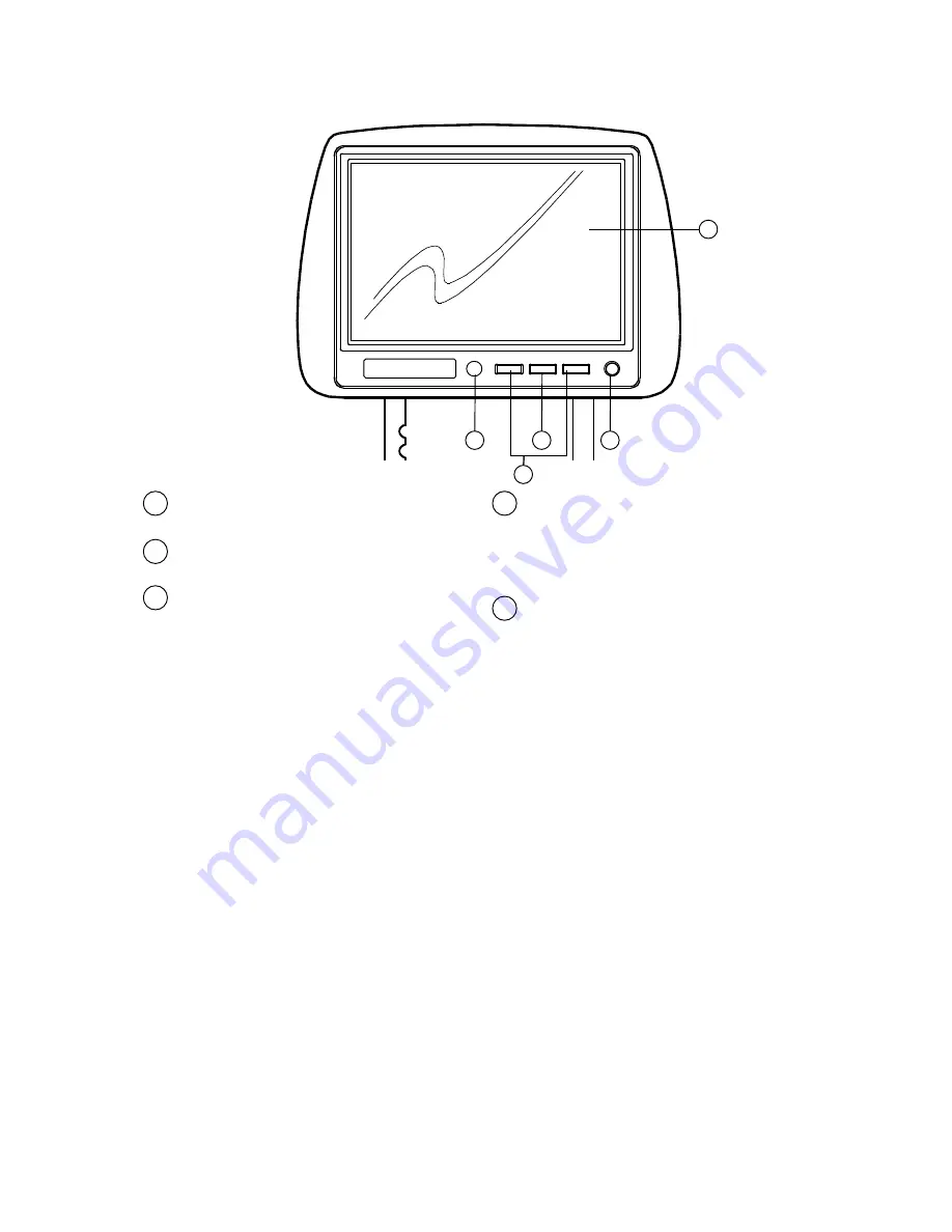
Monitor Controls and Features
HR8-PAK User’s Manual - page 4
Troubleshooting
HR8-PAK User’s Manual - page 8
HR8-PAK User’s Manual - page 5
HR8-PAK User’s Manual - page 6
Remote Control Features
Specifications
• Do not operate this equipment while
driving – safe driving should always
be your highest priority.
• Do not install this product in a location
which allows the monitor screen to be
visible to the driver of the vehicle. In
some states and countries, the viewing
of images on a screen inside a vehicle
is illegal, even by people other than
the driver. Be sure that the installation
and operation of this system is in
compliance with local rules and
regulations.
• Do not open or attempt to repair this
unit yourself. Dangerous high voltages
are present which may result in electric
shock. Refer any repairs to a qualified
service technician.
• Do not attempt to repair a damaged,
broken or faulty power cord. Replace
it with a new one immediately.
• To avoid risk of electronic shock or
damage to the monitor, do not permit
any of this equipment to become damp
or wet from water or drinks. If this does
occur, immediately unplug the power
cord and send the monitor to your
local dealer or service center as soon
as possible.
• If there is smoke or any peculiar odor
present during use or if there is damage
to any of the component enclosures,
immediately unplug the power cord
and send the monitor to your local
dealer or service center as soon as
possible .
When first unpacking your new video
monitor, please check first that the
package contains all of the items
below. If something is missing, contact
the store where you purchased the
player.
• One pair of universal headrests
with built-in 8-inch TFT video
monitors
• Remote control
• On pair of adapter tubes (needed
when replacing headrests with large
diameter posts
• Video/power interface cable
with inline fuse
If you experience operation or performance problems with this product, compare your
installation with the electrical wiring diagram on the previous page. If problems persist,
read the following troubleshooting tips which may help eliminate the problems.
Remove the existing headrest from the seat.
Adjust the spacing of the posts of your new headrest monitor to match those of the
holes in the seatback. To do so, grasp one post in each hand, and push one forward
and one back while pull them apart (to increase the distance) or push them together
(to reduce the distance).
Compare the outside diameter of the new headrest posts with the holes in the seatback.
If the holes in the seatback are significantly larger than the new headrest posts, you
may need to use the adapter tubes (included). These tubes are approximately 12mm
in diameter. If needed, slide an adapter tube onto each of the headrest posts.
Insert the cable into the proper hole in the seatback and feed the cable down into the
seatback and out the bottom (if you are unable to do this properly, see a professional
mobile video installer).
Insert the headrest posts into the seatback and pull the cables from below the seat
to take up the slack. Run them to the location of the video source unit (such as a DVD
player) and connect the wires as shown in the System Wiring diagram.
Installing the monitor
2
General precautions
2
Safety precautions
3
Installation precautions
3
Operation precautions
3
Features
3
What is included?
4
Monitor controls and features
4
Headrest installation
5
Remote control features
5
Changing the remote control
battery
6
System wiring
7
On-screen menu system (OSD)
7
Display presets
8
Troubleshooting
8
Specifications
Congratulations on your purchase
of a this video monitor system.
It has been designed, engineered and
manufactured to bring you the highest
level of performance and quality, and
will afford you years of viewing
pleasure.
page
HR8-PAKG
HR8-PAKB
HR8-PAKT
Universal Headrests with
Pre-installed 8” TFT Monitors
VIDEO SYSTEM
Screen size
LCD panel type
Compatibility
Resolution, pixels
Brightness
Video inputs
GENERAL
Power requirements
Power consumption
Dimensions
All specifications subject to change without notice.
MODEL
HR8-PAKG • HR8-PAKB • HR8-PAKT
Universal Headrests with
Pre-installed 8” TFT Monitors
HR8-PAKG
HR8-PAKB
HR8-PAKT
Universal Headrests with
Pre-installed 8” TFT Monitors
USER’S MANUAL
AVA ENTERPRISES, INC. 3451 LUNAR COURT, OXNARD CA 93030
SYMPTOM
CAUSE
REMEDY
VIDEO INPUT 2
(YELLOW)
FUSE
VIDEO
OUTPUT
This monitor features preset combinations of settings for Picture, Brightness, Color
and Contrast (called Standard, Strong and Soft). You may prefer these to setting
up your own using the OSD system. Press MODE on the remote control to access
these presets.
(Note: Access to these presets is only available through use of the
remote control).
Display presets (Mode Button on Remote)
VIDEO INPUT 1
(YELLOW)
VIDEO
OUTPUT
HR8-PAK
LCD DISPLAY
1
1
2
4
5
3
IR REMOTE CONTROL SENSOR
2
UP/DOWN BUTTONS
Use these buttons for changing
settings within the OSD (On-Screen
Display) menu system
3
MENU BUTTON
Press this button to enter the OSD
(On-Screen Display) menu system
for controlling various parameters
for the display.
4
POWER ON/OFF
5