www.soundskulptor.com
Document revision 1.2 – Last modification : 17/07/20
LA502 Assembly guide – Meter
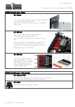
23. Chassis
It is now necessary to assemble the chassis and main PCB to
make a guide for soldering the LED's.
Attach the side plate to the front panel with two M3x6mm
black screws.
24. LED's (1)
Place the main PCB on the side plate and attach it
temporarily with two M3x25mm spacers.
Insert the LED PCB connector into the socket on the main
PCB.
Place the first LED in its hole, longest lead above PCB,
shortest lead below. Push the LED forward as far as
possible against the front panel and solder the top lead.
Repeat the process for all six LED's.
25. LED's (2)
When done, remove the chassis
from the main PCB by unscrewing
the two 25mm spacers, unplug the
LED's PCB and solder the short
lead of the LED's on the bottom
side of the LED's PCB.
LA502 Assembly guide – Final assembly
26. Chassis & PCB
Re-plug the LED's PCB and put the main PCB in place on the chassis.
Attach with four M3x25mm spacers and four lock washers.
27. Knobs
Attach the 2 knobs to the 2 potentiometers.
Copyright ©2017 to Today SoundSkulptor


