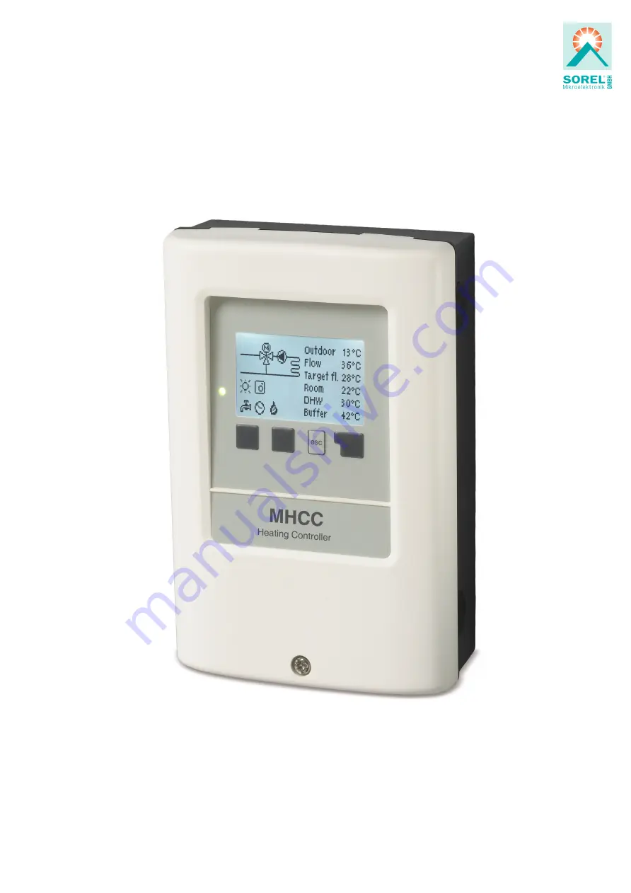
Heating Controller MHCC
Weather-compensated heating circuit controller
Installation and operating instructions
Read carefully before installation, commissioning and operation
Страница 1: ...Heating Controller MHCC Weather compensated heating circuit controller Installation and operating instructions Read carefully before installation commissioning and operation...
Страница 2: ...14 Daylight saving time 14 Heating Circuit Day 14 Heating Circuit Comfort 14 4 Operating mode 15 Manual 15 5 Settings 15 Operating mode 15 S W Day 15 S W Night 15 Curve 15 Day Correction 16 Night Cor...
Страница 3: ...er Technical Data The valid accident prevention regulations VDE regulations the regulations of the local power utility the applicable DIN EN stand ards and the installation and operating instruction o...
Страница 4: ...t has been manufactured and tested with regard to high quality and safety requirements The unit is subject to the stat utory guarantee period of two years from the date of sale The warranty and liabil...
Страница 5: ...tatistical graphics l Extensive setting menus with explanations l Menu block can be activated to prevent unintentional setting changes l Resetting to previously selected values or factory settings Sco...
Страница 6: ...clemp voltage output Max load by external devices 24V 2W Max cable length Pt1000 sensor 10m CAN 3m at 3m a shielded twisted pair cable must be used Isolate shielding and connect it to the protective...
Страница 7: ...to be complete Under no circumstances should the controller replace any safety devices Depend ing on the specific application additional system and safety components such as check valves non return v...
Страница 8: ...voltage output 24 V DC voltage output for external devices Max load by external devices 24V 2W Terminal Connection for N Pump R1 Pump N Mains phase conductor L Mains phase conductor N Neutral Mixer R2...
Страница 9: ...d by the controller If the settings in the controller allow it the sensor is used to alter the flow temperature The switch changes the operation mode of the controller In Timer mode the temperature is...
Страница 10: ...igure 2 and connect electrical system to the controller 4 Suspend clip room cover again and close with the screw 5 Turn on mains supply and operate the controller Electrical Connection Before working...
Страница 11: ...area to be measured Only use immersion pipe mounted or flat mounted sensors suitable for the specific area of application with the appropriate permissible temperature range Low voltage cables such as...
Страница 12: ...flashes quickly red when an error is present Entries are made using 4 keys 3 4 to which contextual functions are assigned The esc key 3 is used to cancel an entry or to exit a menu If applicable a re...
Страница 13: ...llowing pages and check if further settings are necessary for your application 1 Measurement values Serve to display the current measured temperatures If error appears on the display instead of the me...
Страница 14: ...for time date and operating times for the heating circuit The associated temperature reference values are specified in Menu 5 Settings Time Date Serve to set the current time and date For system data...
Страница 15: ...ating mode Heating Automatic Normal mode using the set times Reference Value Fixed flow temperature regardless of the outdoor temperature The desired flow temperature must be set in Menu 4 3 14 days r...
Страница 16: ...g hours because with certain outdoor tem peratures the building might not be optimally heated with the set heating curve With a non optimised heating curve the following situations frequently occur ho...
Страница 17: ...ture of 48 C or 4 8V 43 C corresponds to 4 3V 0 5V offset 4 8V corresponds to 48 C CAN Request is made via the CAN bus the heat request must be activated switching or modulating on a controller in the...
Страница 18: ...ion off or setting the minimum flow temperature too low can lead to severe damage to the system Min Flow The minimum flow temperature is the lower limit of the heating curve and by this the reference...
Страница 19: ...to its delivery state All of the controller s parametrization statistics etc will be lost irrevocably The controller must then be commissioned once again Mixer Here individual parameters for mixer con...
Страница 20: ...e expert menu under Network Choose the Room Controller with the CAN Bus ID of the corresponding controller Eco Display Mode In Eco Display Mode the backlight of the display is switched off if no butto...
Страница 21: ...main completely accessible despite the menu lock being activated and can be used to make adjustments if necessary 1 Measurement values 2 Statistics 3 Times 8 Menu lock 9 Service values 9 Service value...
Страница 22: ...ecialist Sensor x defective Means that either the sensor sensor input on the controller or the connection line is or was defective see Temperature Resistance Table for Pt1000 Sensors on page 11 Restar...
Страница 23: ...rollers in this connection in series must be fitted with terminating resistance The wiring of the two CAN sockets is arbitrary 3 Optionally the data logger can also be connected to the CAN bus Tips Th...
Страница 24: ...ation cannot be excluded Subject as a basic principle to errors and technical changes Date and time of installation Name of installation company Space for notes Your specialist dealer Manufacturer SOR...