background image

XR-L240

21

21

R651

R853

C741

R643

R642

Q734

C731

R721

R722

R723

R724

D721

C454

C456

C458

C460

C450

R450

R452

R454

D622

R459

R461

R460

R458

C421

C422

C424

C423

C425

R420

R421

C732

C403

C426

C161

C400

D750

R752

R622

C622

Q621

C620

C165

C160

C412

C414

C453

R453

R621

R620

C621

Q620

R751

Q651

C750

Q652

C733

R733

Q733

C452

C451

R451

Q452

Q453

R457

Q451

Q450

R500

R501

R732

R730

R731

Q720

Q732

R650

D650

C742

C743

Q741

R740

R644

Q725

R720

Q721

C721

D720

C720

D740

C640

R641

D640

R401

C164

C710

D710

Q722

Q730

C730

D731

D620

D450

C82

C81

Q740

Q640

R753

Q750

C722

C410

C420

C413

C401

C464

C465

C466

C467

R81

C740

R640

D501

D500

D502

D503

D504

D506

D507

D722

C440

C441

C442

C443

D505

C402

IC400

Q731

C734

IC2

Q650

R652

D651

D741

L710

C415

C416

R456

R455

R850

R851

R810

R410

C411

R411

IC500

C502

C507

C501

C506

C500

C503

C505

R503

R502

C504

C504

F901

CN700

100k

0

0.01

4.7k

47k

2PD601AR

0.01

2.2k

2.2k

2.2k

2.2k

11ES2

0.22

0.22

0.22

0.22

2.2
50V

220

220

10k

1SS133

47k

47k

47k

47k

0.0015

2.2
50V

0.1

0.033

0.1

12k

6.8k

100
10V

470p

1

50V

2.2
50V

22

10V

1SS355

27k

2.2k

2.2
50V

PDTC144EK

47

16V

0.01

2.2

50V

2.2
50V

0.1

2.2
50V

220

10k

47

1

PDTA114EK

47k

2PD601AR

0.1

PDTC144EK

470p

27k

DTB113ZK

2.2
50V

2.2
50V

220

DTC314TK

DTC314TK

10k

DTC314TK

DTC314TK

1k

10k

470

10k

2.2k

PDTA124EK

PDTC114EK

1k

MTZJ18B

100
10V

0.047F

5.5V

2PD601AR

22k

100k

PDTC114EK

22k

2PB709AR

0.047

1SS355

1

50V

11ES2

1

50V

47k

MTZJ18B

10

0.01

3300

16V

1N5404TU

2SA1428

2SD1760

10

16V

MTZJ9.1C

MTZJ7.5C

MTZJ3.9B

0.1

0.1

2SA1428

2PD601AR

100

2PB709AR

3.3
50V

1

50V

1

50V

0.033

0.1

470p

470p

470p

470p

100k

10

16V

4.7k

11ES2

11ES2

11ES2

11ES2

11ES2

11ES2

11ES2

11ES2

10p

10p

10p

10p

11ES2

47

16V

LC75421M

2PB709AR

22

25V

PST3443UL

PDTC114EK

1k

MTZJ7.5C

HZS6B2L

0.1

1 50V

10k

10k

0

0

100k

12k

0.0015

6.8k

10

16V

0.1

0.1

10

16V

0.047

0.01

0

10A
32V

16P

1

2

3

4

5

6

7

8

9

10

11

12

13

14

15

16

E4

E1

E3

E8

E2

E9

B14

E7

E5

E6

E10

A1

GND

FRONT LCH+

REAR LCH+

REAR RCH+

FRONT RCH+

FRONT LCH-

REAR LCH-

REAR RCH-

FRONT RCH-

GND

ANT REM

ANT REM

ACC

ACC

BATT

BATT

FL-

FL+

RL-

RL+

RL IN

GND

RR IN

RR+

RR-

FR+

FR-

GND

VCC2

GND

RIPPLE

FL IN

FR IN

VCC1

GND

MUTE

VREF

R1

R2

R3

R4

R5

RSEL0

RIN

RTRE

RBASS1

RBASS2

RSB

ROUT

RFIN

RFOUT

RROUT

VDD

CL

L1

L2

L3

L4

L5

LSEL0

LIN

LTRE

LBASS1

LBASS2

LSB

LOUT

LFIN

LFOUT

LROUT

VSS

CE

DI

FL+

RL+

RR+

FR+

AMP

ANT

ACC

GND

FL-

RL-

RR-

FR-

ILL IN

TEST

BATT

(CHASSIS)

(CHASSIS)

STBY

MUTING

MUTING

MUTING

MUTING

INPUT SELECT,

ELECTRICAL

VOLUME

Q720-722,725

B+ SWITCH

+8.5V REGULATOR

Q731,732

REGULATOR

CONTROL

SWITCH

Q733,734

B+ SWITCH

TUNER

CONTROL

SWITCH

Q620,621

MUTING

GENERATOR

RESET SIGNAL

VSS

NC

VDD

VOUT

B+ SWITCH

Q651,652

BATTERY

DETECT

BATTERY

DETECT

Q740,741

+5V REGULATOR

ACCESSORY

CHECK

(POWER)

POWER AMP

TA8272H

TDA7386 (TYPE B)

(TYPE A)

(TYPE B)

TAB

BEEP

GND

GND

(TYPE B)

(TYPE A)

(TYPE B)

(TYPE B)

(TYPE A)

C506

0.022

1

(TYPE B)

(TYPE A)

(TYPE B)

(TYPE A)

C507

10 16V

47 16V

(TYPE B)

(TYPE A)

(TYPE B)

(TYPE A)

R502

R503

47k

10k

2.2k

22

250

µ

H

REAR RCH+

REAR RCH-

FRONT RCH+

FRONT RCH-

FRONT LCH+

FRONT LCH-

REAR LCH+

REAR LCH-

5-4.

SCHEMATIC  DIAGRAM  – MAIN Board (2/2) –

 See page 24 for IC Block Diagram.

 Refer to servicing note (page 2) for discrimination of TYPE A/B.

(Page 20)

Ver 1.2

Содержание XR-L240

Страница 1: ... 62 dB stereo 68 dB mono Harmonic distortion at 1 kHz 0 7 stereo 0 5 mono Separation 33 dB at 1 kHz Frequency response 30 15 000 Hz M W L W Tuning range MW 531 1 602 kHz LW 153 279 kHz Aerial terminal External aerial connector Intermediate frequency 10 7 MHz 450 kHz Sensitivity MW 30 µV LW 50 µV Power amplifier section Outputs Speaker outputs sure seal connectors Speaker impedance 4 8 ohms Maximum...

Страница 2: ...C 11 2 9 Head Playback HP901 12 3 MECHANICAL ADJUSTMENTS 13 4 ELECTRICAL ADJUSTMENTS Tape Deck Section 14 Tuner Section 15 5 DIAGRAMS 5 1 Note for Printed Wiring Boards and Schematic Diagrams 18 5 2 Printed Wiring Board MAIN Board 19 5 3 Schematic Diagram MAIN Board 1 2 20 5 4 Schematic Diagram MAIN Board 2 2 21 5 5 Printed Wiring Board CONTROL Board 22 5 6 Schematic Diagram CONTROL Board 23 5 7 I...

Страница 3: ...n 11 12 qk PTY programme type button 13 ql DSPL display mode change button 6 9 w OFF button 5 Warning when installing in a car without ACC accessory position on the ignition key switch Be sure to press OFF on the unit for two seconds to turn off the clock display after turning off the engine When you press OFF momentarily the clock display does not turn off and this causes battery wear SENS AF 1 2...

Страница 4: ... nicht hinderlich ist Bauen Sie das Gerät so ein daß es keinen hohen Temperaturen keinem direkten Sonnenlicht keiner Warmluft von der Heizung keinem Staub keinem Schmutz und keinen starken Vibrationen ausgesetzt ist Für eine sichere Befestigung verwenden Sie stets nur die mitgelieferten Montageteile Hinweis zum Montagewinkel Das Gerät sollte in einem Winkel von weniger als 20 montiert werden Insta...

Страница 5: ...o connect passive speakers to these terminals 1 Note for the aerial connecting If your car aerial is an ISO International Organization for Standardization type use the supplied adapter 7 to connect it First connect the car aerial to the supplied adapter then connect it to the aerial jack of the master unit Hinweise zum Anschlußdiagramm Hinweise zu den Steuerleitungen Die Motorantennen Steuerleitun...

Страница 6: ...rt werden wenden Sie sich bitte an den Autohändler Schéma de connexion d alimentation Le connecteur d alimentation auxiliaire peut varier suivant le type de voiture Vérifiez le schéma du connecteur d alimentation auxiliaire de votre voiture pour vous assurer que les connexions correspondent Il en existe trois types de base illustrés ci dessous Il se peut que vous deviez intervertir la position des...

Страница 7: ...m Umgang mit der Halterung vorsichtig damit Sie sich nicht die Hände verletzen Nehmen Sie vor der Installation das Schutzmaterial 6 ab Avertissements Remarque importante pour la manipulation du support 1 Manipulez précautionneusement le support pour éviter de vous blesser aux doigts Déposez le collier de protection 6 avant l installation Attenzione Avvertenza sulla manipolazione della staffa 1 Man...

Страница 8: ... described in can be performed in any order Note 2 Without completing the process described in the next process can not be performed Note 3 Illustration of disassembly is omitted SET 2 2 SUB PANEL Page 8 FRONT PANEL SECTION Note 3 COVER Note 3 2 3 MECHANISM DECK MG 36SZ12 32 Page 9 2 4 MAIN BOARD Page 9 2 5 HEAT SINK Page 10 2 6 BRACKET MD Page 10 2 7 MOTOR CAPSTAN REEL M901 Page 11 2 8 MAIN BELT ...

Страница 9: ...MG 36SZ12 32 2 two screws BTP2 6 6 1 connector CN350 1 connector CN300 3 mechanism deck MG 36SZ12 32 2 two screws BTP2 6 6 2 4 MAIN BOARD 2 two ground point screws PTT2 6 6 3 two screws BTP2 6 6 3 screw BTP2 6 6 4 main board 1 claw ...

Страница 10: ...XR L240 10 2 5 HEAT SINK 1 five screws PTT2 6 10 1 two screws PTT2 6 10 2 heat sink 2 6 BRACKET MD 1 claw 1 claw 1 claw 2 four screws B2 6 4 3 bracket MD ...

Страница 11: ...b belt C 2 main belt Note When installing motor adjust the screw and screw hole of motor 2 8 MAIN BELT SUB BELT C 1 main belt 4 sub belt c 2 screw PTP2 3 A 2 screw PTP2 3 2 screw PTP2 3 2 screw PTP2 3 3 Lift up the bottom BKT TS in the direction of arrow A as far as the belt can be removed ...

Страница 12: ...ster arm blue head HP901 head lead wire adjuster arm blue HEAD LEAD WIRE COLOR INDICATION ON HEAD HP901 AND SLIDE SW BOARD 0 SPG support plate 7 PSW reel B 8 HP roller A qa adjuster arm SPG A qs adjuster arm SPG B qf head playback HP901 6 slide SW board 4 Remove the three solders of head lead wires yellow lead wire black lead wire red lead wire slide SW board ...

Страница 13: ...ter Meter Reading 2 46 5 39 mN m Forward CQ 102C 25 55 g cm 0 35 0 76 oz inch Forward 0 15 0 39 mN m CQ 102C 1 5 4 g cm Back Tension 0 02 0 06 oz inch 2 46 5 39 mN m Reverse CQ 102RC 25 55 g cm 0 35 0 76 oz inch Reverse 0 15 0 39 mN m CQ 102RC 1 5 4 g cm Back Tension 0 02 0 06 oz inch 4 91 14 70 mN m FF REW CQ 201B 50 150 g cm 0 69 2 08 oz inch TEST MODE This set have the test mode function In the...

Страница 14: ...r P 4 A063 6 3 kHz 10 dB head azimuth adjustment WS 48A 3 kHz 0 dB tape speed adjustment Adjustment Location PB head Tape Speed Adjustment Setting Procedure 1 Put the set into the FWD PB mode 2 Adjust adjustment resistor for inside capstan motor so that the reading on the frequency counter becomes in 3 015 Hz Specified Value 2 940 to 3 090 Hz Adjustment Location See page 17 level meter test tape P...

Страница 15: ...ay indication 8 2 to 8 6 Adjustment Location See page 17 FM Auto Seek Stop Level Adjustment Setting TUNER button FM Procedure 1 Set to the test mode see page 13 2 Push the TUNER button and set to FM Display 3 Adjust with the volume RV3 on TU100 so that the FM indi cation turns to FM0 indication on the display window But in case of already indicated FM0 turn the RV3 so that put out light 0 indicati...

Страница 16: ...kHz deviation 26 7 19 kHz pilot 7 5 kHz deviation 10 0 01 µF set antenna jack ANT100 speaker out terminal level meter 10 kΩ MW Auto Seek Stop Level Adjustmant Make this adjustment after FM Auto Seek Stop Level Adjust ment Setting TUNER button MW Procedure 1 Set to the test mode see page 13 2 Push the TUNER button and set to FM 3 Push the MODE button and set to MW Display 4 Adjust with the volume R...

Страница 17: ...0 Adjustment Location Set Upper View TU100 RV2 FM Stereo Separation Adjustment RV100 FM RDS S Meter Adjustment Tape Speed Adjustment RV3 FM Auto Seek Stop Level Adjustment RV1 MW Auto Seek Stop Level Adjustment ...

Страница 18: ... normal produc tion tolerances Waveforms are taken with a oscilloscope Voltage variations may be noted due to normal produc tion tolerances Circled numbers refer to waveforms Signal path F FM f MW LW E TAPE PLAYBACK L BUS AUDIO IN Abbreviation AMBER Amber illumination type GREEN Green illumination type Note on Printed Wiring Board X parts extracted from the component side Y parts extracted from th...

Страница 19: ... C710 CN700 POWER 16 8 9 1 F901 18 17 19 D722 Q722 R722 R721 R26 X1 R43 X200 R622 R501 R34 R33 R32 C7 D721 IC500 25 24 1 2 D500 D501 D503 D502 C507 D290 Q290 C291 D622 D620 C503 C622 C620 R104 R102 R206 C208 C150 D150 R207 C420 C400 C354 C161 C124 C422 C426 C402 D450 C452 C451 C450 C453 C416 C412 C410 C125 C355 C160 1 26 TU100 FM AM TUNER UNIT 14 13 C360 C353 R364 D250 CN600 1 2 11 12 A CONTROL BO...

Страница 20: ...XR L240 20 20 5 3 SCHEMATIC DIAGRAM MAIN Board 1 2 See page 24 for Waveforms See page 24 for IC Block Diagram Page 23 Page 21 ...

Страница 21: ...6V MTZJ9 1C MTZJ7 5C MTZJ3 9B 0 1 0 1 2SA1428 2PD601AR 100 2PB709AR 3 3 50V 1 50V 1 50V 0 033 0 1 470p 470p 470p 470p 100k 10 16V 4 7k 11ES2 11ES2 11ES2 11ES2 11ES2 11ES2 11ES2 11ES2 10p 10p 10p 10p 11ES2 47 16V LC75421M 2PB709AR 22 25V PST3443UL PDTC114EK 1k MTZJ7 5C HZS6B2L 0 1 1 50V 10k 10k 0 0 100k 12k 0 0015 6 8k 10 16V 0 1 0 1 10 16V 0 047 0 01 0 10A 32V 16P 1 2 3 4 5 6 7 8 9 10 11 12 13 14 ...

Страница 22: ... 1 683 564 11 11 D934 S969 976 SEEK AMS CONTROL BOARD CONDUCTOR SIDE PL902 LCD BACK LIGHT PL901 LCD BACK LIGHT D961 A K R954 C952 R913 R912 D960 A K R955 R918 R917 D962 A K C953 C955 C954 1 20 21 40 41 60 61 80 IC900 D963 K A R911 R900 R910 2 12 11 1 CN900 A MAIN BOARD CN600 R905 R904 R903 R902 R901 R920 R921 R932 R931 R930 R916 R915 R919 R914 D964 K A 1 683 564 11 11 1 2 3 4 5 6 7 8 9 10 11 A B C...

Страница 23: ...XR L240 23 23 5 6 SCHEMATIC DIAGRAM CONTROL Board See page 24 for Waveform Page 20 ...

Страница 24: ...US SLAVE TRANSCEIVER 17 18 CIN 19 LVIN 20 8 7 DATA CLOCK DATA CLOCK 4 4 5 9 10 3 4 5 IC400 LC75421M TLM 36 35 34 33 1 2 CCB INTERFACE CONTROL CIRCUIT LOGIC CIRCUIT CONTROL CIRCUIT 32 31 30 29 28 27 26 25 24 23 22 21 20 19 R VREF 4 5 6 7 8 9 10 11 12 13 14 15 16 17 18 L VREF 3 LROUT LFOUT LFIN LOUT LSB LBASS2 LBASS1 LTRE LIN LSELO L5 L4 L3 L2 L1 VSS VDD RROUT RFOUT RFIN ROUT RSB RBASS2 RBASS1 RTRE ...

Страница 25: ...et 25 LCD CE O Chip enable signal output to the liquid crystal display driver H active 26 KEYACK I Key acknowledge signal detect input from the liquid crystal display driver 27 DAVN RDS I RDS data request signal input from the RDS decoder H active 28 B U IN I Battery detect signal input from the battery detect circuit L is input at low voltage 29 NC Not used 30 RAM BU I Internal RAM reset detectio...

Страница 26: ...power on H AM power on Not used 61 to 68 NC Not used 69 NOISE ON O Discharge control signal output for the noise detection circuit H discharge 70 to 82 NC Not used 83 ILL COLOR I Illumination color select input terminal L amber illumination H green illumination fixed at L 84 DEST SEL0 I Destination setting terminal fixed at H 85 DEST SEL1 I Destination setting terminal fixed at L 86 DEST SEL2 I De...

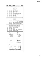
Страница 27: ...abinet s Color F901 2 2 2 3 3 TU100 Front panel section 1 16 2 3 4 5 6 7 8 9 10 11 12 13 14 15 MG 36SZ12 32 Ref No Part No Description Remark Ref No Part No Description Remark 1 3 224 905 01 PANEL SUB 2 X 3370 437 2 LOCK ASSY 3 3 041 581 01 DOOR CASSETTE 4 3 044 125 01 SPRING TORSION 5 3 376 464 11 SCREW PTT 2 6X6 GROUND POINT 6 1 757 662 11 CORD WITH CONNECTOR ISO POWER 7 X 3378 167 1 COVER ASSY ...

Страница 28: ...72 01 SPRING F R 62 3 224 915 11 BUTTON FF M 63 3 224 907 01 BUTTON D BASS POS D BASS OFF 64 3 236 752 01 BUTTON SEEK SEEK MANU 65 3 224 927 01 PLATE LCD GROUND 66 1 694 696 31 CONDUCTIVE BOARD CONNECTION 67 3 224 926 11 ILLUMINATOR 68 3 236 754 01 PLATE LIGHT GUIDE 69 3 224 924 01 HOLDER LCD 70 1 786 304 11 SWITCH SHEET 71 3 224 904 01 PANEL FRONT BACK 72 A 3315 467 A PANEL ASSY FRONT 73 X 3378 4...

Страница 29: ... 045 932 01 ADJUSTER ARM SPG A 111 3 045 939 01 PINCH ARM SPG F 112 3 045 891 01 PINCH ARM F 113 3 045 906 01 ADJUSTER SHIM X 114 3 045 952 01 MACHINE SCREW M1 7X4 115 3 713 786 51 SCREW P 2X3 117 3 045 893 01 REEL SPINDLE 119 A 3220 846 A MECHANISM DECK ASSY MG 36SZ12 32 HP901 1 500 661 11 HEAD PLAYBACK M901 1 763 507 11 MOTOR CAPSTAN REEL S901 1 771 928 11 SWITCH SLIDE DIRECTION S902 1 771 926 1...

Страница 30: ...etal film resistor METAL OXIDE Metal oxide film resistor F nonflammable Items marked are not stocked since they are seldom required for routine service Some delay should be anticipated when order ing these items SEMICONDUCTORS In each case u µ for example uA µA uPA µPA uPB µPB uPC µPC uPD µPD CAPACITORS uF µF COILS uH µH Refer to servicing note page 2 for discrimi nation of TYPE A B When indicatin...

Страница 31: ...AMIC CHIP 0 01uF 10 25V C165 1 162 970 11 CERAMIC CHIP 0 01uF 10 25V C200 1 107 826 11 CERAMIC CHIP 0 1uF 10 16V C201 1 162 916 11 CERAMIC CHIP 12PF 5 50V C202 1 164 315 11 CERAMIC CHIP 470PF 5 50V C203 1 162 916 11 CERAMIC CHIP 12PF 5 50V C204 1 107 826 11 CERAMIC CHIP 0 1uF 10 16V C205 1 162 964 11 CERAMIC CHIP 0 001uF 10 50V C208 1 124 589 11 ELECT 47uF 20 16V C209 1 107 826 11 CERAMIC CHIP 0 1...

Страница 32: ...11 ELECT 3 3uF 20 50V C730 1 126 791 11 ELECT 10uF 20 16V C731 1 162 970 11 CERAMIC CHIP 0 01uF 10 25V C732 1 104 665 11 ELECT 100uF 20 10V C733 1 164 315 11 CERAMIC CHIP 470PF 5 50V C734 1 128 551 11 ELECT 22uF 20 25V C740 1 126 157 11 ELECT 10uF 20 16V C741 1 162 970 11 CERAMIC CHIP 0 01uF 10 25V C742 1 124 584 00 ELECT 100uF 20 10V C743 1 125 701 11 DOUBLE LAYER 0 047F 5 5V C750 1 107 826 11 CE...

Страница 33: ... RES CHIP 100 5 1 10W R30 1 216 057 00 METAL CHIP 2 2K 5 1 10W R31 1 216 025 11 RES CHIP 100 5 1 10W R32 1 247 807 31 CARBON 100 5 1 4W R33 1 247 807 31 CARBON 100 5 1 4W R34 1 247 807 31 CARBON 100 5 1 4W R41 1 216 025 11 RES CHIP 100 5 1 10W R43 1 247 807 31 CARBON 100 5 1 4W R61 1 216 097 11 RES CHIP 100K 5 1 10W R62 1 216 295 00 SHORT CHIP 0 R65 1 216 097 11 RES CHIP 100K 5 1 10W R68 1 216 295...

Страница 34: ...S CHIP 47K 5 1 10W R643 1 216 065 00 RES CHIP 4 7K 5 1 10W R644 1 216 097 11 RES CHIP 100K 5 1 10W R650 1 249 417 11 CARBON 1K 5 1 4W R651 1 216 097 11 RES CHIP 100K 5 1 10W R652 1 249 417 11 CARBON 1K 5 1 4W R700 1 216 073 00 RES CHIP 10K 5 1 10W R701 1 249 421 11 CARBON 2 2K 5 1 4W R702 1 249 421 11 CARBON 2 2K 5 1 4W R703 8 719 200 82 DIODE 11ES2 R704 1 260 300 11 CARBON 4 7 5 1 2W R705 1 216 0...

Страница 35: ...REW B 2 6X4 6 7 627 553 27 PRECISION SCREW P 2X2 5 TYPE3 7 7 685 101 11 SCREW PTP 2X3 NON SLIT 8 7 621 255 35 SCREW P 2X5 9 7 621 772 18 SCREW P 2X4 10 7 685 781 09 SCREW PTT 2X4 S ACCESSORIES 3 236 756 11 MANUAL INSTRUCTION ENGLISH FRENCH DUTCH ITALIAN GERMAN 3 236 757 11 MANUAL INSRTUCTION INSTALL ENGLISH FRENCH DUTCH ITALIAN GERMAN X 3378 490 2 CASE PANEL ASSY for FRONT PANEL PARTS FOR INSTALLA...

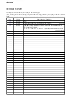
Страница 36: ...sed page allows you to jump to the next revised page Ver Date Description of Revision 1 0 2001 10 New 1 1 2002 07 Correction of Part No for INSULATED PLATE ECN CSA05430 1 2 2002 11 Change of parts mounted on MAIN board with the consequence of IC500 on MAIN board Correction of Part No for Ref No 119 MECHANISM DECK ASSY ECN CSA06163 SPM 02011 ...

Отзывы: