background image

134

Using UMID Data


A

ppen

dix

Using UMID Data

Metadata is additional information recorded on media 
along with audio-visual data. It is used to bring greater 
efficiency to the flow of operations from material 
acquisition through editing, and to make it easier to find 
and reuse material.
As one of application of metadata, the UMID has been 
internationally standardized.

What is a UMID?

A UMID (Unique Material Identifier) is a unique identifier 
for audio-visual material defined by the 
SMPTE-330M-2004 standard.
A UMID may be either as a 32-byte Basic UMID or an 
Extended UMID, which includes an additional 32 bytes of 
Source Pack to make a total 64 bytes.

For details, refer to SMPTE-330M.

A globally unique ID is automatically recorded for every 
clip.

The Extended UMID is metadata that provides additional 
information such as location, time/date, company ID and 
so on.
The UMID is applied as follows.

Using the Extended UMID

You have to enter a country code, organization code and 
user code. 
Set the country code referring to the table in ISO 3166, and 
set the organization code and user code according to the 
guidelines of your organization.

For details, see “Setting UMID ownership information” 
(page 135).

Functions of UMID data

UMID data enables the following:
• Addition of a globally unique ID to every clip of audio-

visual material. The unique ID is used to detect the 
material source and to link it with the original source 
material.

• Distinguishing between original material and copied 

material. 00 is added to the Instance Number for original 
material.

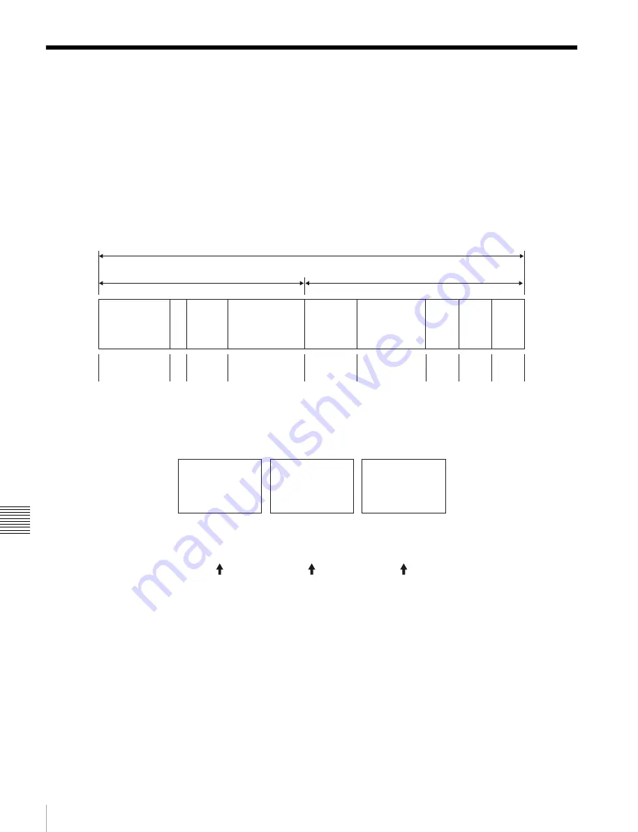
Extended UMID (64 bytes)

Basic UMID (32 bytes)

Source Pack (32 bytes)

Universal label

L

Instance 
No.

Material Number

Time/Date

Spatial 
Coordinates

Country

Org

User

12 bytes

1

3 bytes

16 bytes

8 bytes

12 bytes

4 bytes 4 bytes 4 bytes

Instance No.

Material No. 
ID generated when 
shooting 
Same as the above

Source Pack 
Shooting 
information (when, 
where and who) 
Same as the above

Original material: 00 00 00 
Copied material: generation number (1 byte)

+ random number (2 bytes)

Distinguish between the 
original material and copied 
material

Material source ID/
detecting material

Metadata pack that 
identifies the source of 
material unit by defining the 
when, where and who of 
the material unit with which 
it is associated.

Содержание XDS1000

Страница 1: ...glish 1st Edition Revised 6 The supplied CD ROM includes operation manuals for the XDS 1000 Professional Media Station English Japanese French German Italian Spanish and Chinese versions in PDF format For more details see Using the CD ROM Manual on page 15 ...

Страница 2: ... is installed in a rack please make sure that the internal air ambient temperature of the rack is within the specified limit of this product 4 Prevention against achieving hazardous condition due to uneven mechanical loading When this product is installed in a rack please make sure that the rack does not achieve hazardous condition due to uneven mechanical loading 5 Install the equipment while tak...

Страница 3: ...eil qu à un personnel qualifié CET APPAREIL DOIT ÊTRE RELIÉ À LA TERRE Lors de l installation de l appareil incorporer un dispositif de coupure dans le câblage fixe ou brancher la fiche d alimentation dans une prise murale facilement accessible proche de l appareil En cas de problème lors du fonctionnement de l appareil enclencher le dispositif de coupure d alimentation ou débrancher la fiche d al...

Страница 4: ...raussendung EN55103 2 Elektromagnetische Verträglichkeit Störfestigkeit Für die folgenden elektromagnetischen Umgebungen E1 Wohnbereich E2 kommerzieller und in beschränktem Maße industrieller Bereich E3 Stadtbereich im Freien und E4 kontrollierter EMV Bereich z B Fernsehstudio Dieses Produkt wurde von oder für Sony Corporation 1 7 1 Konan Minato ku Tokio 108 0075 Japan hergestellt Bei Fragen zur P...

Страница 5: ...and Functions of Parts Front Panel 16 Display screen 21 Rear Panel 26 Chapter 3 Preparations Supplying Power 31 Initial Setup 31 Front Panel Tilt Mechanism 33 Connections and Settings 34 Connections for using Content Browser and non Sony nonlinear editors 34 Connections for cut editing 34 Synchronization Reference Signals 39 Setting System Frequency 40 Setting Time Data 40 Setting timecode 40 Sett...

Страница 6: ...s 53 Preparations for editing 53 Editing operations 54 Preread editing 54 Playback 55 Selecting a clip or an EDL 57 Playback operation 57 Playback operations using thumbnails 59 Chase play 59 Copying 60 Overview 60 Copy operations 60 Chase copy 63 Transcode copy 64 Handling of the Internal Storage When Recording Does Not End Normally Salvage Function 64 Chapter 5 Operations in Clip List Screens Ov...

Страница 7: ... media 80 Chapter 6 File Operations Overview 81 Directory structure 81 File operation restrictions 82 FTP File Operations 84 Making FTP connections 84 Command list 84 Recording Continuous Timecode with FTP Connection 89 CIFS File Operations 89 Making CIFS connections 89 Chapter 7 Menus Menu System Configuration 90 Setup Menu 90 Items in the basic menu 91 Basic menu operations 94 Menu bank operatio...

Страница 8: ... UMID Data 134 Ancillary Data 136 Ancillary data in HDSDI SDSDI signals 136 Ancillary data in MXF files 137 General MXF metadata 137 Closed caption data 137 Correspondence between Setting Items of the HKDV 900 and Setup Menu of This Unit 142 Trademarks and Licenses 143 MPEG 4 visual patent portfolio license 143 MPEG 2 video patent portfolio license 143 About IJG Independent JPEG Group 143 Characte...

Страница 9: ...8 kHz uncompressed PCM recording format for high sound quality 1 MPEG HD422 is a trademark of Sony Corporation HDDs for internal storage Long recording times This unit is equipped with hard disk drives HDDs for internal storage These HDDs provide 1 terabyte TB of data storage allowing you to record up to about 30 hours in the HD422 50 Mbps recording format High reliability This unit is equipped wi...

Страница 10: ...ear editing function1 The unit can function as a recorder to support insert editing and assembly editing of recorded clips 1 Installation of the optional XDBK 105 is required SD upconvert function The unit is provided with an upconvert function You can input SD signals to the HD SD SDI INPUT connector and record them as HD signals HD downconvert function The unit is provided with a downconvert fun...

Страница 11: ...t the panel to the angle that makes the buttons easiest to use Supports a variety of interfaces This unit supports the following interfaces HD SDI video 8 channel audio input and output 1 HD SDI video 8 channel audio monitor output 1 SD SDI video 8 channel audio input and output SD SDI video 8 channel audio monitor output 1 SD composite output SD composite monitor output DVB ASI TS input and outpu...

Страница 12: ... Ingesting editing system see page 13 Live production system see page 14 Broadcast delivery system see page 14 PDW 700 PMW 500 HKDV 900 Video Control Unit VDCP controller BVE 700 Headphones HDW 2000 series PDW F1600 HD1500 SxS memory cards SxS PRO SxS 1 PDW 1500 SD video monitor HD video monitor Audio monitor PC monitor Laptop computer Broadcast station reference timecode 1 The unit cannot be cont...

Страница 13: ...nd backup recorder On the satellite truck Computer installed with Content Browser Camcorder SDI signal This unit Save to internal storage DVB ASI TS signal DVB ASI TS signal This unit Playout Archive system Camcorder Reuse media Computer ingestion controller Remote control via Internet Protocol Web Service API Line input SDI DVB ASI TS signal Camcorder Recording data This unit Global Ethernet Nonl...

Страница 14: ...n which this unit is used as both server and backup player Slow motion replay controller RS422 VDCP Camcorder Live video SID signal This unit SDI signal Monitor Slow motion replay video Global Ethernet FTP CIFS Nonlinear editing system pre post editing Computer installed with Content Browser Nonlinear editing system Material server Recording system Global Ethernet MXF file Computer program transmi...

Страница 15: ...he United States and or other countries Reading the CD ROM manual To read the operation manual contained on the CD ROM do the following 1 Insert the CD ROM in your CD ROM drive A cover page appears automatically in your browser If it does not appear automatically in the browser double click on the index htm file on the CD ROM 2 Select and click on the operation manual that you want to read This op...

Страница 16: ...he HOME page of the function menu see page 44 b LEVEL volume adjustment knob Adjust the volume of headphones with this knob You can also cause this knob to simultaneously adjust the output volume from the ANALOG AUDIO MONITOR OUTPUT2 R 1 L 2 connectors on the rear panel To do this set setup menu item 114 AUDIO MONITOR OUTPUT LEVEL to variable 1 Port and media selection section see page 17 1 PHONES...

Страница 17: ...onnector for maintenance g REMOTE button Press this button turning it on to perform remote control of this unit from a device connected to the REMOTE 9P R P2 and P1 connectors This allows you to control the recording and playback ports individually h KEY INHI inhibit switch This turns key operation inhibit mode on or off 1 Port and media selection section This unit has a recording port and a playb...

Страница 18: ...s 5 to 8 using the function menu For details see P3 AUDIO page page 46 By the setting of setup menu item 131 AUDIO VOLUME you can enable the CH 1 ALL CH adjustment knob to simultaneously adjust all eight channels When this simultaneous adjustment is enabled the ALL CH indicator lights b VARIABLE audio level adjustment selector switch This selects whether input audio levels or playback audio levels...

Страница 19: ... a list of clips or EDLs edit decision lists saved on the currently selected media is displayed That is the current screen is switched to a clip list screen When pressed again returns to the basic operation screen or the video monitor screen e MENU button Starts the setup menu and starts the Clip Menu from a clip list screen see page 69 The same information is also superimposed on the display on a...

Страница 20: ...first clip Hold down the SHIFT button and press this button b PLAY button To start playback press this button turning it on c NEXT button Press this button turning it on to jump to the next clip and show the first frame During chase play play jumps to the last frame that is playable at that time This button is also used together with other buttons for the following operations Forward direction hig...

Страница 21: ...ere are no detents In shuttle mode the playback speed varies in the range 20 times normal speed according to the angular position of the dial There is a detent at the center position for still image playback In variable speed mode you can make fine adjustments to the playback speed over the range from 2 to 2 times normal speed according to the angular position of the dial There is a detent at the ...

Страница 22: ...Displays the reference level for recording as set in the maintenance menu F Level bars Display the audio recording or playback levels of channels 1 to 8 The OVER indicators light when the audio level exceeds 0 dB 1 Function menu 2 Audio input display audio level meters 3 System information 4 Media status display 5 Recording playback format 6 Clip information 7 Operation status display 8 Time data ...

Страница 23: ...ecording playback format In 1 in 1 out mode this displays the recording format when a record port is selected or the playback clip format when a playback port is selected In VTR mode this displays the format of the clip being played f Clip information Displays clip information The display varies depending on the clip playback mode 1 1 The clip playback mode setting is switched using maintenance me...

Страница 24: ...unt mode is set with DF NDF on page P4 TC of the function menu see page 46 i Status display area A Error warning and alarm messages Messages about operations and the status of the unit appear here The seriousness of the message is indicated by the color as follows Red Error message flashing Orange Warning message White Alarm message B Current EDL icon Lights when a current EDL is specified C Delet...

Страница 25: ...en recording to the internal storage is being performed I Playback display Lights when a clip on the internal storage or memory card is in the open state Video monitor screen A Superimposed information Appears when CHAR SEL on the HOME page of the function menu is set to ON B Sub status information Displayed when setup menu item 017 SUB STATUS DISPLAY SELECT is set to Off in the setup menu When me...

Страница 26: ...e setting of the REC PB2 PORT and PB1 PORT buttons on the front panel Allows you to connect a device with an HDMI input connector such as an HD projector or a high definition TV Audio output signals are the signals of the channels selected with MONITR L and MONITR R on the HOME page of the function menu 1 HD SD SDI signal input output section see page 27 1 PCIe expansion slot 3 HDMI OUTPUT connect...

Страница 27: ...nd setup menu of this unit i GPIO general purpose I O connector When you are using this unit in a larger system such as a playout system this connector allows you to connect an external device to control this unit s playback and to return tally and alarm signals to the external device j MONITOR connector Outputs the same video that appears on the display of this unit s front panel as analog RGB co...

Страница 28: ...timecodes or error messages on the output of the 2 SUPER connector with the setting for CHAR SEL on the HOME page of the function menu and with the setting for setup menu item 027 SD CHARACTER You can always disable to superimpose the data independent of the setting for CHAR SEL with the setting for setup menu item 027 See Basic Operations of the Function Menu page 44 for more information about th...

Страница 29: ...s check to be sure that the on standby indicator on the front panel is lit in red showing that this unit is in the standby state and then press the main power switch to the off side b AC power input connector Connect to an AC power supply with the power cord not supplied c Ground terminal U Connect this to ground as required 4 Digital audio signal input output section a DIGITAL AUDIO AES EBU IN di...

Страница 30: ...l 1 and the connector 2 is set to audio channel 2 You can change these settings with setup menu item 824 ANALOG LINE OUTPUT SELECT see page 106 You can set the output level with the maintenance menu item M37 AUDIO CONFIG see page 114 Factory default setting 4 dB Non audio signals are muted c ANALOG AUDIO MONITOR OUTPUT2 R 1 L 2 connectors XLR 3 pin male Output audio signals for monitoring The moni...

Страница 31: ...e the main switch on the rear panel is on to operative state wait at least three seconds after the unit has entered standby state and then press the on standby button on the front panel Initial Setup This unit is shipped with the area of use system frequency and current date and time still unset Therefore you need to make initial setup settings before using the unit You cannot use the unit without...

Страница 32: ...e SET function button F5 The message NOW SAVING appears and the setting screen disappears Then the unit powers itself off and on again To return to the original screen without saving settings Press the RETURN function button F1 To set the date and time Use the maintenance menu item M3D DATE TIME PRESET See page 117 for more information about maintenance menu operations The time zone is reset to th...

Страница 33: ...le of the front panel in position 1 40 degrees position 2 65 degrees or position 3 90 degrees The angle cannot be fixed if you pull the front panel past position 3 all the way out to the return position To fix the front panel return it to position 0 and then pull it out to the desired angle To return the front panel to its original position Unlock the front panel by pulling it out to the return po...

Страница 34: ...allation of Content Browser access the Sony website closest to your area When using the network connector The following shows connection examples The XDS 1000 IP address and other network related settings are required for connections For details of the network related settings see To change network settings page 118 Connecting this unit directly to a laptop computer Connecting three of this unit t...

Страница 35: ...h OFF Audio selection function switching button INPUT button HDSDI Function menu HOME F1 VID IN SDI Function menu page 1 F1 TCG INT Function menu page 1 F2 PR RGN PRESET Function menu page 1 F3 RUN FREE BVE 700 700A editing control unit SYNCHRONIZE menu OFF VTR constants see below This unit player Setup menu item 208 PROTOCOL FOR REMOTE 9P VTR REMOTE button for playback port Lit HD video monitor T...

Страница 36: ...erform tasks such as thumbnail searches because the required VTR constants have been set in advance for connection with XDCAM devices System frequency VTR constant 1 2 3 4 5 6 7 8 9 10 11 12 13 14 15 16 59 94i 59 94P 29 97P A0 B0 00 96 07 07 03 80 0A 07 FE 00 80 5A FF 5A 50i 50P 25P A1 B0 00 7D 07 07 03 80 0A 07 FE 00 80 4C FF 4B 23 98P A2 B0 00 78 07 07 03 80 0A 07 FE 00 80 48 FF 48 HD video moni...

Страница 37: ...D IN SDI Function menu page 1 F1 TCG INT Function menu page 1 F2 PR RGN PRESET Function menu page 1 F3 RUN FREE RM 280 editing controller EDITOR REMOTE CONTROL selector switch EDITOR Setup menu 01 PREROLL 5s Setup menu 05 SYNC SEL ON Setup menu 06 SYNC VTR RECORDER Setup menu 09 EDIT DLY AUTO Setup menu 10 R ST DLY AUTO Setup menu 11 P ST DLY AUTO Setup menu 19 FNC MODE NORMAL This unit player Set...

Страница 38: ...re transferred via a REMOTE 9P connector Settings on each unit For details of HDW M2000 M2000P settings refer to the HDW M2000 M2000P Operation Manual Device Settings HDW M2000 M2000P recorder REMOTE 1 9P button Unlit This unit player Setup menu item 208 PROTOCOL FOR REMOTE 9P VTR REMOTE button for playback port Lit HD video monitor To HD SDI input connector This unit player Reference video signal...

Страница 39: ... a reference signal input to the REF VIDEO INPUT connector The following reference signals can be used 720 59 94P system 1080 59 94i tri level sync signal 525 black burst signal 720 50P system 1080 50i tri level sync signal 625 black burst signal When you directly interconnect video I O connectors between two of this unit or between this unit and the XDS PD1000 PD2000 or PDW F1600 HD1500 F800 700 ...

Страница 40: ...value The following run modes can be selected Free Run Timecode advances continually Rec Run Timecode advances only during recording System TC system timecode mode This records the output of the internal timecode generator synchronized to a broadcast station reference timecode signal input to the SYSTEM TC INPUT connector External Regen regenerate mode This records the output of the internal timec...

Страница 41: ...roadcast station reference timecode signal input to the SYSTEM TC INPUT connector To record with the internal timecode generator synchronized to external timecode External Regen Use this method to synchronize the timecode generators of a number of recorders to record the playback timecode of external VTRs or to record while maintaining synchronization between the source video and timecode Use eith...

Страница 42: ... hexadecimal 0 to 9 A to F Superimposed Text Information The video signal output from the following connectors on this unit contains superimposed text information including timecode and alarm messages HD SDI OUTPUT1 2 SUPER connector SD SDI OUTPUT1 2 SUPER connector HD SDI MONITOR OUTPUT2 2 SUPER connector SD SDI MONITOR OUTPUT2 2 SUPER connector COMPOSITE OUTPUT MONI 2 connector Adjusting the tex...

Страница 43: ...vo lock status or playback speed TCR TC reader timecode UBR TC reader user bits data TCR VITC reader timecode UBR VITC reader user bits data TCG TC generator timecode UBG TC generator user bits data Note Display Operation mode Block A Block B STOP Stop mode NEXT xxx Cuing up to the first frame of the next clip PREV xxx Cuing up to the first frame of the current clip Display Meaning A B F FWD Fast ...

Страница 44: ...you want appears To set the value of the setting item Press the function button to the left of each setting item so that the setting value flashes to enable adjustment of the value and then turn the PUSH SET knob to increase or decrease the value Turning the PUSH SET knob while holding down the SHIFT button increases the increment of adjustment Pressing the function button to the left of each sett...

Страница 45: ... page is set to ON and setup menu item 808 is set to anything other than off F4 A2 INPUT Selects the audio input signal to assign to audio channel 2 SDI Audio signal embedded into SDI signal ANALOG2 Input signal to the ANALOG AUDIO INPUT 2 connector AES EBU2 Signal input to the DIGITAL AUDIO AES EBU IN 1 2 connectors DVB ASI DVB ASI TS signal a Item Setting F5 A3 INPUT Selects the audio input sign...

Страница 46: ...ld the SHIFT button down while you turn the knob F5 Unassigned function button F6 Unassigned function button Item Setting Item Setting F1 TCG Selects the timecode signal to which the internal timecode generator synchronizes INT Follow the initial value set from the front panel or remotely from the device connected to a REMOTE 9P connector EXT Synchronize to external timecode signal input to the TI...

Страница 47: ... Other trademarks and trade names are the property of their respective owners Use the optional QDA EX1 XQD Express Card Adapter if using XQD memory cards Use the following optional accessories when using Memory Stick or SDHC cards MEAD MS01 Memory Stick Adapter for Memory Stick PRO HG Duo HXA series MEAD SD01 SD Card Adapter for SDHC cards F6 TCR Selects the type of timecode to display in the time...

Страница 48: ...hen this unit is used in an environment subject to static electricity or electric noise Do not use or store SxS memory cards in locations that are outside the specified environmental ranges very hot such in as vehicles parked in the sun during summer or exposed to direct sunlight or near heaters subject to high humidity and corrosion When inserting a memory card insert with the label side facing t...

Страница 49: ...may be destroyed Be sure that the MEMORY ACCESS A B lamps are lit in green or off when you turn off the power or remove memory cards Switching between SxS memory cards When SxS memory cards are loaded in both memory card slots A and B press the MEMORY button to select the card you wish to use The MEMORY button is disabled while copying is in progress that is switching is not executed even if you p...

Страница 50: ...the monitor audio Adjust with the LEVEL adjustment knob Carrying out recording When recording with this unit you can perform normal recording or simultaneous recording Normal recording Records to internal storage Simultaneous recording Records simultaneously to internal storage and SxS memory card Simultaneous recording is disabled when maintenance menu item M397 PORT CONFIGURATION is set to VTR M...

Страница 51: ... you insert a recordable SxS memory card when a message is displayed to confirm whether you wish to replace the card and continue the recording or to stop the recording recording to the inserted SxS memory card starts from the position where the recording to the previous card was aborted If continuing simultaneous recording spanning multiple memory cards you can set the overlap between memory card...

Страница 52: ...ith different recording formats exists in the preroll segment that segment cannot be edited Linear Editing For linear editing install the optional XDBK 105 and set the unit to VTR mode To configure VTR mode set maintenance menu item M397 PORT CONFIGURATION to VTR mode Overview You can perform the following types of editing on recorded clips Locked clips cannot be edited Editing across multiple cli...

Страница 53: ...n menu operations See page 94 for more information about setup menu operations Note Notes Item Setting Recording format Check the recording format of the clip with the display window see page 23 and select the same format with setup menu item 031 RECORDING FORMAT Audio Non audio data To perform insert editing of non audio data set maintenance menu item M37 AUDIO CONFIG M372 NON AUDIO INPUT to data...

Страница 54: ...on the original channels or on other digital audio channels For preread editing set PREREAD on page P5 OTHER of the function menu to ON see page 47 In preread editing an I O feedback loop may occur if an input video signal is used as the reference signal To prevent this set OUT REF on the HOME page of the function menu to REF see page 45 This selects use of an external reference signal during prer...

Страница 55: ...torage to either of the following Clip mode The playback target is the currently selected clip only factory default setting Continuous playback mode The playback target is a loop of 100 clips around the clip selected on a clip list display screen If another clip is selected on a clip list display screen or the mode changes from standby off mode to standby on mode controllable via the REMOTE 9P con...

Страница 56: ...nit stops at the position where recording ended To play back a clip press the PREV button to move to the start frame of any clip or press the PREV button with the PLAY button held down to move to any position After playback stops When you press the STOP button playback stops at that position and the position is saved When you press the PLAY button playback starts from the stopped position When pla...

Страница 57: ...f playback Normal playback Playback at normal speed Playback in jog mode Variable speed playback with the speed determined by the speed of turning the jog dial Playback in shuttle mode Variable speed playback with the speed determined by the angular position of the shuttle dial Playback in variable speed mode Variable speed playback with the speed finely determined by the angular position of the s...

Страница 58: ...g to the desired playback speed Playback in shuttle mode starts 4 To stop playback in shuttle mode return the shuttle jog dial to the center position or press the STOP button When setup menu item 101 SELECTION FOR SEARCH DIAL ENABLE is set to dial factory default setting you can start shuttle playback by simply rotating the shuttle jog dial even when the SHTL JOG button is not lit Video and audio ...

Страница 59: ...s The shot marks can also be set during recording For details see page 51 Playback operations using thumbnails Playback operations that you can perform with thumbnails include searching for clips displaying clip information and locking and deleting clip This allows you to check the actual video as you work See Clip Operations page 71 for more information about thumbnail operations Chase play While...

Страница 60: ... clip see page 62 Chase copy When a clip is being recorded to the internal storage SDI recording you can duplicate copy the clip on the internal storage to an SxS memory card at the same time see page 63 Transcode copy You can duplicate or copy a clip on copy source media by changing the video format of the clip see page 64 Transcode partial copy You can perform a transcode copy of the specified p...

Страница 61: ...ip is being recorded to the internal storage or when a clip on the internal storage is being played back 1 Insert an SxS memory card containing recorded clips into a memory card slot 2 Select the copy source media To copy clips on the SxS memory card Press the MEMORY button To duplicate clips on the internal storage Press the INTERNAL button When two SxS memory cards are loaded Press the MEMORY bu...

Страница 62: ... storage you cannot select ALL Select the SxS memory card as the copy destination media in step 7 To copy clips from an SxS memory card to another SxS memory card Insert the copy source and copy destination SxS memory cards then carry out the procedure in Copying clips to the internal storage page 61 In step 2 press the MEMORY button In step 7 select SxS memory card as the copy destination media T...

Страница 63: ...T points are set Format the media Chase copy When a clip is being recorded to the internal storage that clip can also be duplicated copied on the internal storage to an SxS memory card at the same time If FTP connections are made between this unit and a computer see page 84 it is also possible to perform chase copy of clips or files when they are being transferred from the computer It is also poss...

Страница 64: ...NAL in step 7 3 Press the TRANSCOD function button F3 to change the indication to ON 4 Carry out steps 7 and 8 of Copying clips to the internal storage page 61 Handling of the Internal Storage When Recording Does Not End Normally Salvage Function The processing for recording to the internal storage does not end normally if for example the main power switch on the rear panel is turned off during re...

Страница 65: ...w and the thumbnails view of clip list screens Switching between display screens To switch between the basic operation screen video monitor screen and clip list screens thumbnails view and details view press the THUMBNAIL button 1 or DISPLAY button 2 The screens change as shown in the following figure Clip list screen thumbnails view Basic operation screen Video monitor screen Clip list screen det...

Страница 66: ...e thumbnails can be displayed in the thumbnail display area the position of the slider shows the relative position of the currently displayed clips and the length of the slider shows the relative length of currently displayed clips within all of the clips f Clip name Displays the name of the selected clip or EDL When multiple clips are selected displays the name of the first clip or the most recen...

Страница 67: ...playback status icon When the recording media is the internal storage an icon appears to indicate the recording or playback status recording playing 1 chase play 1 Playing means that the clip is open the file is open because the clip has been selected in a clip list screen or elsewhere Therefore the icon appears even during jog play of a clip and during still image display Clip Properties screen W...

Страница 68: ...playback icon playback or recording status icon An unplayable icon appears to indicate that the clip cannot be played or EDL for example because the system frequency settings differ from the current settings of this unit A copy playback icon appears to indicate that the clip cannot be played back directly but copy playback is possible During recording and playback an icon appears to indicate the r...

Страница 69: ...nail move the frame see page 71 Multiple selection frames appear when multiple thumbnails are selected see page 71 b Clip name Displays the name of the clip displayed in the current chapter thumbnail screen c Clip number total number of clips Displays the total number of clips on the selected media and the number of the clip whose chapter thumbnails are currently displayed d Chapter number total c...

Страница 70: ...nal device To override Lock Unlock Clips SHIFT STOP Lock Selected Clips Locks the selected clips Lock All Clips Locks all clips on the selected media Unlock Selected Clips Unlocks the selected clips Unlock All Clips Unlocks all clips on the selected media Set Clip Flag OK Sets the OK flags in the selected clips NG Sets the NG flags in the selected clips KP KEEP Sets the KEEP flags in the selected ...

Страница 71: ...PREV button while holding down the SHIFT button To jump to the last clip Press the NEXT button while holding down the SHIFT button To make a continuous selection of clips Move the selection frame to the first clip that you want to select Then while holding down the SHIFT button turn the PUSH SET knob To cancel the continuous selection move the selection frame without the SHIFT button held down Sea...

Страница 72: ...ils of the chapters in a clip See page 66 for more information about thumbnail view See page 69 for more information about chapter thumbnail screen 1 In the clip thumbnail screen select the thumbnail of a clip or the icon of an EDL with chapters set The S mark see page 68 appears on the thumbnails of clips with chapters set No S marks are displayed on EDL icons 2 Press the PAGE HOME button to disp...

Страница 73: ...ure Adding and deleting shot marks Setting and clearing clip flags Locked clips are deleted along with other clips when a media is formatted Clips cannot be locked or unlocked when a media is write protected To lock clips 1 In a clip list screen select the clips that you want to lock multiple selections possible This step is not needed if you lock all clips 2 Display the Clip Menu 3 Select Lock Un...

Страница 74: ...or information about operations Setting the index picture frame The clip thumbnail screen displays thumbnails as index pictures for clips Normally the index picture is the first frame in a clip but you can change it to any frame in the clip for a different index picture You cannot set index pictures for EDLs 1 In the basic operation screen or video monitor screen play back the clip you want to set...

Страница 75: ... sub clips Sub clips are virtual editing data that specify ranges in the original clips You can use them without modifying the original data The following figure illustrates the relation between clips and sub clips In the above example the whole of clip 2 has been added as sub clip 1 and the whole of clip 4 has been added as sub clip 2 Sub clip 3 is part of clip 3 Therefore when EDL E0001 is playe...

Страница 76: ... OUT setting window appears on the bottom right The time codes for the OUT point and duration DUR are displayed in the IN OUT setting window and the OUT indicator is lit 5 Press the PAGE HOME button to display the function menu and press the CREATE NEW EDL F3 button The EDL creation starts The name for the created EDL appears when the creation finishes The created EDL becomes the current EDL When ...

Страница 77: ...set 1 On the video monitor screen cue the frame you want to specify for the IN point 2 Press and hold the button and then press the PUSH SET knob The IN OUT setting window appears on the bottom right of the display The timecode for the IN point is displayed in the IN OUT setting window and the IN indicator is lit 3 Cue the frame you want to specify for the OUT point 4 Press and hold the button and...

Страница 78: ...e PUSH SET knob The current EDL is released and the current EDL icon is removed from the status display area To reference the current EDL Referencing the current EDL displays the chapter thumbnail screen for the current EDL This operation is performed on clip list screens 1 Display the P1 EDL page of the Clip F menu 2 Press the GOTO CURT EDL function F6 button The currently specified current EDL i...

Страница 79: ...ard into the memory card slot When the confirmation dialog appears asking if you want to execute formatting execute step 6 once more 7 When formatting is completed select Exit and then press the PUSH SET knob Repairing SxS memory cards If an SxS memory card is not recognized correctly you can repair the memory card for use by rebuilding the SxS memory card management data The repair operation can ...

Страница 80: ... Consequently remote connections to internal storage are not disconnected when performing the operation described below 1 Display a clip list screen on the display 2 Display the Clip F menu 3 Switch to the P2 OTHER page using the PAGE HOME button and press the NET ENA F6 button When remote connection is permitted ALL is displayed under the NET ENA menu on the P2 OTHER page When disconnected INTERN...

Страница 81: ... with the maintenance menu item M33 FILE I F CONFIG FOLDER STYLE To use a directory structure matching existing XDCAM devices Select xdcam style To use a directory structure supporting multiple media Select xds style factory defaults setting The following figure shows the directory structure example This structure is not the same as the actual structure recorded on the internal storage Example whe...

Страница 82: ... file and a M02 KLV file with the same name in the part are also deleted automatically Directories cannot be created in the Clip directory You can select the MXF format for Read operation in setup menu item 155 For details see page 98 Edit directory Note File name Content Operations Read Write Rename Create Delete DISCMETA XML Contains metadata to indicate the HDD properties Yes Yes a No No No MED...

Страница 83: ...not be created in the Edit directory Sub directory Directories cannot be created in the Sub directory General directory UserData directory When connected by CIFS only reading is supported MEMORY A directory MEMORY B directory M01 XML a Metadata file generated automatically when E01 SMI file is created Yes Yes b No c No d No e Other files Files other than the above No No File name Content Operation...

Страница 84: ...ction Properties uncheck the Internet Protocol Version 6 TCP IPv6 and then click the OK button Making FTP connections FTP connections between this unit and a remote computer can be made with either of the following The command prompt FTP client software This section explains how to use the command prompt For more information about using FTP client software refer to the documentation of the FTP cli...

Страница 85: ...62000 PASV This command requests this unit to listen on a data port which is not its default data port It puts this unit into passive mode waiting for the remote computer to make a data connection Command syntax PASV CRLF TYPE Specifies the type of data to be transferred Command syntax TYPE SP type code options delimited by SP CRLF type code can be any of the following However for XDS devices data...

Страница 86: ...te computer to the current directory on this unit Depending on the type of file transferred the following files are created MXF file M01 XML file metadata M02 KLV file user metadata E01 SMI file M01 XML file metadata For MXF files or E01 SMI files the UMID of the copy source file is not saved However it is saved if an immediately preceding SITE UMMD extended command has been issued For E01 SMI fil...

Страница 87: ...r directory Command syntax CWD SP path name CRLF Moves to a directory as follows depending on whether a directory is specified with path name Directory specified To the specified directory No specification To the root directory Input example CWD Clip CDUP Moves one level up in the directory structure makes the parent of the current directory be the current directory Command syntax CDUP CRLF MKD Cr...

Страница 88: ... body however data from sixth frame through 150th frame is only transferred SITE TCPR Presets the starting timecode of a clip copied with the STOR command Specify the timecode in the format ffssmmhh ff frames ss seconds mm minutes hh hours This command remains in effect until a STOR command is executed or if no STOR command is executed until the FTP connection is terminated If a SITE UMMD command ...

Страница 89: ...tions using the Common Internet File System CIFS between this unit and the computer Preparations See Preparations under FTP File Operations page 84 Making CIFS connections CIFS connections between this unit and a Windows computer can be made with either of the following Use Windows Explorer to map this unit as a network drive Refer to this unit directly from Windows Explorer The following describe...

Страница 90: ...perating hours meter the text information superimposed on the video output to the monitor the menu banks for retaining menu settings Extended menu This menu is used to make a wide range of settings relating to the functions of this unit for example the control panel functions video and audio control and digital data processing Configuration of the basic menu The basic menu comprises the following ...

Страница 91: ...ation output from the HD SDI OUTPUT1 2 SUPER SD SDI OUTPUT1 2 SUPER HD SDI MONITOR OUTPUT2 2 SUPER SD SDI MONITOR OUTPUT2 2 SUPER or COMPOSITE OUTPUT MONI 2 connector for superimposed display on the monitor The hexadecimal value 00 is for the far left of the screen Increasing the value moves the position of the characters to the right 00 to 0C to 28 When the number of system lines is 1080 and the ...

Страница 92: ...s are enabled 009 CHARACTER TYPE Determine the type of characters such as timecode output from the HD SDI OUTPUT1 2 SUPER connector the SD SDI OUTPUT1 2 SUPER connector the HD SDI MONITOR OUTPUT2 2 SUPER connector the SD SDI MONITOR OUTPUT2 2 SUPER connector or the COMPOSITE OUTPUT MONI 2 connector for superimposed display on the monitor white White letters on a black background black Black letter...

Страница 93: ...7 SD CHARACTER Specify whether to superimpose text information on the SD video signal Sub item 1 SD SDI2 b Specify whether to superimpose text information on the video signal output from the SD SDI OUTPUT1 2 SUPER connector off Do not superimpose on Superimpose 2 MONITOR SD b Specify whether to superimpose text information on the video signal output from the SD SDI MONITOR OUTPUT2 2 SUPER or COMPO...

Страница 94: ...1 3 c EXT NAMING Set how to assign the clip name for recording DVB ASI input signals disable dis Assign the clip name set with PREFIX and NUMERIC enable ena Assign the same clip name as on the DVB ASI signals 038 SD CHARACTER V POSITION Set the vertical position of the timecode and other text character information output on the COMPOSITE OUTPUT MONI 2 SD SDI OUTPUT1 2 SUPER and SD SDI MONITOR OUTP...

Страница 95: ...e saving operation is completed the video monitor screen returns to its normal indications If you power off the unit before a save operation is completed settings may be lost Wait until the save is completed before powering off the unit If instead of pressing the SAVE function button F5 you press the MENU button the new settings are not saved The message ABORT appears on the video monitor screen f...

Страница 96: ...ton to display the setup menu 2 Press the RESET button The message INITIALIZE ALL ITEMS TO FACTORY PRESET VALUES appears to confirm whether you wish to return all settings to their factory default settings 3 Press the SAVE function button F5 The message NOW SAVING appears on the video monitor screen while the settings of all items are returned to their factory default settings These factory defaul...

Страница 97: ...e Settings column are the values that appear in settings screens The values in brackets are the value shown in menu screens when they differ from the values shown in settings screens The underlined values are the factory defaults Note Menu items in the 100s relating to the control panels Item number Item name Settings 101 SELECTION FOR SEARCH DIAL ENABLE Select how the unit enters the shuttle jog ...

Страница 98: ...se output with FTP CIFS perform output in the MXF format compatible with previous devices supporting Professional Discs disable memory style mem Do not perform chase output with FTP CIFS perform output in the MXF format compatible with previous devices supporting SxS memory cards enable growing style ena Perform chase output with FTP CIFS perform output in the MXF format unique for chase output Th...

Страница 99: ...rlap 1 min 1 m 1 minute overlap Menu items in the 200s relating to the remote control interface Item number Item name Settings 208 PROTOCOL FOR REMOTE 9P Select the protocol used with a REMOTE 9P connector for each port Sub item 1 2 PB Select the protocol used with the playback port VTR Sony 9 pin VTR protocol VDCP VDCP protocol Note When maintenance menu item M397 PORT CONFIGURATION is set to VTR...

Страница 100: ...a 317 AUDIO EDIT MODE a Select the type of audio transition used for linear editing cut edit cut Cut editing audio discontinuity at transition point and possible noise during playback cross fade cross Cross fade 319 PREREAD SELECT a Select the preread operation audio video a v Preread for both audio and video audio Preread for audio only video Preread for video only 320 DIGITAL AUDIO PB PROCESS ON...

Страница 101: ...31 is set to auto and the VITC insertion line is set to line 16 In 59 94i 59 94P 29 97P mode UC output of wide picture information is given priority if OUTPUT in setup menu item 731 is set to auto and the VITC insertion line is set to line 20 In 50i 50P 25P mode Select the line into which to insert VITC signals SD output 9H to 21H to 22H Any line from line 9 through line 22 Note You can insert VIT...

Страница 102: ... s first frame REC TCG PB Zero Base menu 0 Timecode for recording depends on the settings of the menu items related to the timecode generator Timecode for cueing is generated taking 00 00 00 00 as the timecode value of the clip s first frame 651 UMID SDI OUTPUT Select whether to output UMID in the VANC of the SDI output off Do not output on Output See Using UMID Data page 134 for more information ...

Страница 103: ...s 12 to 19 blank blnk Carry out blanking throu thru Switch off blanking LINE 20 Specify blanking for line 20 blank blnk Carry out blanking half Carry out half blanking throu thru Switch off blanking In 59 94i 59 94P 29 97P mode J LINE 12 LINE 20 Specify blanking for lines 12 to 20 blank blnk Carry out blanking throu thru Switch off blanking LINE 21 Specify blanking for line 21 blank blnk Carry out...

Страница 104: ...the output signal 0 0 7 5 In 59 94i 59 94P 29 97P mode J Add the setup level selected by this item to the output signal 0 0 7 5 715 VIDEO GAIN CONTROL a b Adjust the video output level of SD video signals output from the SD SDI OUTPUT COMPOSITE OUTPUT or HDMI OUTPUT connectors 2048 to 0 to 848 716 CHROMA GAIN CONTROL a b Adjust the chroma output level of SD video signals output from the SD SDI OUT...

Страница 105: ...r H phase 512 to 0 to 511 731 WIDE MODE a Specify whether to record and play back with the addition of wide picture information Sub item 1 INPUT Select whether to save wide picture information when recording auto Automatically save wide picture information when it is detected in the selected input video signal on Always save wide picture information off Never save wide picture information 2 OUTPUT...

Страница 106: ...ater for values greater than 80 80 128 samples approx 2 7 ms 80 1 sample approx 20 μs 0 to 80 to FF Values can be set in this range 808 INTERNAL AUDIO SIGNAL GENERATOR Select the operation of the internal audio test signal generator off Do not output test signal silence silnc Silent signal 1kHz sine 1kHz 1 kHz 20 dB FS sine wave signal When you set the INT SG item on page P1 INPUT of the function ...

Страница 107: ...signed to audio output channels 3 and 4 tr7 8 Tracks 7 and 8 assigned to audio output channels 3 and 4 831 TS OUT AUDIO MODE a b Select the number of audio output channels for DVB ASI TS signals 4ch 4 channels 2ch 2 channels Menu items in the 900s relating to digital process Item number Item name Settings 920 SD SDI H ANC CONTROL a Select whether to add information to the SDI output Sub item 1 AUD...

Страница 108: ...r decimal You can set this in units of 1 or 20 when the SHIFT button is held down When sub item TS MODE of menu item 926 is set to HDV 6 OUTPUT MODE Selects the output mode Packet packt Packet mode Burst Burst mode 7 PACKET LENGTH Selects the packet length 188Byte 188B 188 bytes 204Byte 204B 204 bytes 8 META PACKET OUT Specifies output of DVB ASI TS signal metadata packets on Output metadata packe...

Страница 109: ...1FFE in 1 units or 20 units when the SHIFT button is held down When sub item TS MODE of menu item 926 is set to HDV Note Do not use the same PID value as for any other sub item 930 DOWN CONVERTER MODE a Select the down converter mode EDGE CROP CROP Select the edge crop mode LETTER BOX L BOX Select the letter box mode SQUEEZE SQUEZ Select the squeeze mode 931 DOWN CONVERTER LETTER BOX MODE a Select...

Страница 110: ...tem 950 is set to EDGE CROP 120 to 0 to 120 952 LETTER BOX POSITION UC a When menu item 950 is set to LETTER BOX adjust the vertical location of the position where the picture is cut out for up converter output in letter box mode 120 to 0 to 120 953 UP CONVERTER PROCESS a Select the source picture to use in converting SD to HD FIELD Use field pictures ADAPTIVE ADAPT Frame or field is selected auto...

Страница 111: ...ode SQUEEZE SQUEZ Select the squeeze mode 3 H CROP P When sub item CONVERT is set to CROP adjust the H crop horizontal crop position for up converter output in edge crop mode 120 to 0 to 120 4 L BOX P When sub item CONVERT is set to L BOX adjust the vertical location of the position where the picture is cut out for up converter output in letter box mode 120 to 0 to 120 5 CNV PROC Select the source...

Страница 112: ...NU then press the PUSH SET knob or the SELECT function button F2 The setting screen for M40 EXTENDED MENU appears 4 Turn the PUSH SET knob to select ENABLE and press the SAVE function button F5 The message NOW SAVING appears on the video monitor screen while the new settings are saved in memory When the saving operation is completed the video monitor screen returns to its normal indications When y...

Страница 113: ...n states REDUNDANT PSU Set whether to install the optional XDBK 101 and make power supply redundant ON Make redundant OFF Do not make redundant DVB ASI I O Specify whether to install the optional PDBK 202 on Install off Do not install M3 OTHERS Other setting items Item Setting M30 SOFTWARE VERSION Display of the software version of this unit M31 SERIAL NUMBER Display of the serial number and Media...

Страница 114: ...edia command of the Clip Menu disable dis Disable the Format Media command enable ena Enable the Format Media command M397 PORT CONFIGURATION Set the port operation mode 1 in 1 out mode i o Ports operate independently VTR mode vtr Ports operate together as input and output connectors M398 VDCP STATUS MODE Set the operations to reflect in the VDCP status VDCP vdc Only operations via VDCP are reflec...

Страница 115: ...t possible to set the same line with menu items M3B0 M3B1 and M3B2 If the same line is specified priority is given in the order of M3B0 M3B1 and M3B2 for example if the same line is specified with M3B0 and M3B1 the setting with M3B1 is ignored When VANC data is output to HD SDI playback signals the number of the output VANC line is the same as that of the input VANC line When a UMID or essence mar...

Страница 116: ...sign an IP address automatically with the DHCP server DISABLE dis Do not assign automatically ENABLE ena Assign automatically M51 IP ADDRESS Set the IP address of this unit 192 168 001 010 Notes IP address cannot be set when DHCP is set to ENABLE To check the automatically acquired IP address of this unit close the maintenance menu and then open it again M52 SUBNET MASK Set the subnet mask 255 255...

Страница 117: ...the setting 3 Press the PUSH SET knob or the SELECT function button F2 to confirm the setting change 4 Press the SAVE function button F5 The message NOW SAVING appears on the video monitor screen while the new settings are saved in memory When the saving operation is completed the video monitor screen returns to its normal indications M5F RESET NET CONFIG Reset network settings to the factory defa...

Страница 118: ... a different digit to be changed Use the B and b buttons To change the value of a digit Turn the PUSH SET knob Turning clockwise increases the value and turning counterclockwise decreases the value The V and v buttons can also be used To return to the factory default setting Press the RESET button 4 When all digits are set press the SAVE function button F5 This returns to the NETWORK menu 5 Repeat...

Страница 119: ... 7 Menus This returns to the NETWORK menu 5 In the NETWORK menu press the SAVE function button F5 6 When the message NETWORK CONFIG WAS CHANGED PLEASE REPOWER appears power the unit off and then on again with the on standby button ...

Страница 120: ... or cold operating temperature range 5 C to 40 C 41 F to 104 F Remember that in summer or in warm climates the temperature inside a car with the windows closed can easily exceed 50 C 122 F In damp or dusty locations Locations where the unit may be exposed to rain Locations subject to violent vibration Near strong magnetic fields Close to radio or TV transmitters producing strong electromagnetic fi...

Страница 121: ... strap Wait for 30 seconds after turning the power off For a brief interval after the power is turned off the platters inside the HDD will still keep spinning and the heads will be in an insecure position During this interval the unit is more susceptible to shocks and vibrations than during normal operation For a period of at least 30 seconds after turning the power off avoid subjecting the unit e...

Страница 122: ... mode Displays the total number of hours the unit has been powered on in units of 1 hour H11 OPERATION HOURS mode resettable Same as H01 except that the count is resettable This can be used as a guide in determining when to replace parts To display the operating hours meter Press the MENU button to display the setup menu then turn the PUSH SET knob to display the required item H01 or H11 To reset ...

Страница 123: ... AFTER ABOVE PROCEDURE Reset the settings in the setup menu see page 90 If the same message appears after you reset the settings contact your Sony service or sales representative Exchg batt BATTERY NEEDS REPLACING PLEASE CONTACT SERVICE The battery of the internal clock is exhausted Contact your Sony service or sales representative Run Software Update Program RUN SOFTWARE UPDATE PROGRAM The softwa...

Страница 124: ...s memory card cannot be used Under Repair of Media A B MEDIA A B IS BEING REPAIRED Automatic repair for the management area of the memory card is in progress Wait until the automatic repair is complete Repair Failed A B REPAIR FAILED The memory card is damaged and recording and playback are not possible Replace the memory card Alarm message in status display area Description action KEY INHI This a...

Страница 125: ...e recorded Delete unneeded shot marks 0 to 9 in the chapter thumbnail screen Illegal Operation This appears when an attempt is made to carry out an invalid operation Media is not Ready The media is in the course of being mounted or has not been loaded Alarm message in status display area Alarm message in video monitor screen Description action Input Sig VIDEO INPUT SIGNAL DOES NOT MATCH SYSTEM SET...

Страница 126: ...orted by this unit so copy operation is impossible Copy Aborted The copy operation was aborted Some Clip s are Locked Some of the selected clips are locked protected Clip Error The clip is substandard so the copy operation failed Set Appropriate IN OUT Points The settings of IN and OUT points for partial copy operation are not proper Check the IN and OUT point settings No Clip The clip selected fo...

Страница 127: ...status display area Alarm message in video monitor screen Description action No INPUT INPUT VIDEO IS NOT DETECTED CHECK THE VIDEO INPUT MODE AND SUPPLY A VIDEO SIGNAL TO VIDEO INPUT Check the setting of V INPUT on page P1 INPUT of the function menu see page 45 Input an HD SDI signal EMPHASIS INPUT AUDIO EMPHASIS IS NOT SUPPORTED CHECK THE EMPHASIS OF THE AUDIO INPUT SIGNAL Check the emphasis of th...

Страница 128: ...Sony service or sales representative Rebuilding xx REBUILDING NOW PLEASE DO NOT TURN OFF Data is being rebuilt Do not power the unit off until the rebuild has finished CONFIG MIS INTERNAL STORAGE CONFIGURATION MISMATCH Check whether the required number of hard disk drives is installed If that does not solve the problem contact your Sony service or sales representative Low Remaining Capacity The in...

Страница 129: ... mm 16 3 4 5 1 4 18 1 8 inches Mass 15 5 kg 34 lb 2 7 oz Power requirements 90 V to 264 V AC 47 Hz to 63 Hz Power consumption 170 W Inrush current 1 Maximum possible inrush current at initial switch on Voltage changes caused by manual switching 32 A peak 7 A r m s 240 V AC 2 Inrush current after a mains interruption of five seconds Voltage changes caused at zero crossing 13 A peak 5 A r m s 240 V ...

Страница 130: ...0 dB S N Y 53 dB or more Y C delay 20 ns or less K factor K2T 1 0 or less Processor adjustment range Video level to 3 dB Chroma level to 3 dB Set up black level 30 IRE 210 mV Chroma phase 30 System phase SYNC 15 µs SC 0 to 400 ns Audio performance Sampling frequency 48 kHz Quantization 24 bits Headroom 20 dB 18 dB 16 dB 12 dB 9 dB EBU level selectable Frequency response 20 Hz to 20 kHz 0 5 1 0 dB ...

Страница 131: ...ith AES 3id 1995 Timecode output TIME CODE OUT BNC type 1 SMPTE timecode 1 0 Vp p 75 Ω unbalanced Remote control connectors REMOTE 9P D sub 9 pin 2 female complying with RS 422A VIDEO CONTROL D sub 9 pin 1 female complying with EIA RS 423 GPIO D sub 15 pin 1 input CMOS 5 V output open collector network RJ 45 type 1 1000BASE T complying with IEEE802 3ab 100BASE TX complying with IEEE802 3u 10BASE T...

Страница 132: ... program number for DVB ASI TS can be set with the setup menu item 926 DVB ASI SETTING see page 108 If a system frequency of 720 59 94P or 720 50P is selected set function menu item F6 OUT REF to INPUT Video resolution system frequency 1440 1080 59 94i 50i 29 97P 25P 1920 1080 59 94i 50i 29 97P 25P 1280 720 59 94P 50P When the system frequency is 23 98P input output of DVB ASI TS signals is imposs...

Страница 133: ...he same name as that of clips being fed For this it is necessary to set sub item EXT NAMING of setup menu item 036 FILE NAMING to enable on this unit and set sub item META PACKET OUT of setup menu item 926 DVB ASI SETTING to on on the feeder unit Menu settings Setting the number of audio output channels for DVB ASI TS signals Setup menu item 831 TS OUT AUDIO MODE Switching DVB ASI input output and...

Страница 134: ...table in ISO 3166 and set the organization code and user code according to the guidelines of your organization For details see Setting UMID ownership information page 135 Functions of UMID data UMID data enables the following Addition of a globally unique ID to every clip of audio visual material The unique ID is used to detect the material source and to link it with the original source material D...

Страница 135: ...character input location then press the knob 3 Use the PUSH SET knob or function button F3 or F4 to select characters to input at the selected location To delete all input data Press the RESET button 4 Press SAVE function button F5 The message NOW SAVING appears and the ownership information is saved About the UMID ownership information COUNTRY country code Set the country code by entering an abbr...

Страница 136: ...ata packets 1 EIA Electronic Industries Alliance 2 ARIB Association of Radio Industries and Businesses To record ancillary data In maintenance menu item M3B VANC RX PARAMETER set the lines where ancillary data is inserted the DID Data Identifier word and the SDID Secondary Data Identifier word see page 115 To record and playback EIA 708 B standard closed caption data in HDSDI signals Set the follo...

Страница 137: ... only when the DATA ITEM of the head frame is identified as ANC Frame Elements conforming to the SMPTE436M 2006 when an MXF file is input General MXF metadata This unit examines the data contained in the header metadata area 1 when an MXF file is input If the data is identified as the data created by the device other than XDCAM at this time one file KLVE file is created 1 The header metadata area ...

Страница 138: ...ions Recording and playback after EIA 608t708 conversion and down convert playback In response to closed caption input data that complies with the EIA 608 standard record play and output that data after conversion to EIA 708 format By performing down convert playback you can also play and output EIA 608 standard closed caption data However settings are required for recording of EIA 608 standard cl...

Страница 139: ...8 B standard closed caption data in SDSDI line 21 signals after conversion to the EIA 708 B standard when the optional XDBK 103 is installed page 136 Cross convert playback of HD clips containing closed caption data and down convert playback When you cross convert and play 1080 or 720 clips EIA 708 compliant closed caption data recorded in the clips is played and output with no changes By performi...

Страница 140: ...lips are played after cross conversion EIA 608 standard closed caption data recorded in the clips is played and output without conversion By performing down convert playback you can also play and output EIA 608 standard closed caption data However settings are required for output of EIA 608 standard closed caption data For details see To record and playback EIA 708 B standard closed caption data i...

Страница 141: ... Cross convert and playback Down convert playback Down convert playback HDSDI VANC output 1080 playback SDSDI line 21 output Composite line 21 output HDSDI VANC output 720 playback SDSDI line 21 output Composite line 21 output Playback of HD clips ...

Страница 142: ...745 SETUP LEVEL HD HD Sync Phase 746 SYNC PHASE HD UC HD Fine 747 FINE HD UC D1 Master No menu item corresponds to this setting item D1 Y No menu item corresponds to this setting item D1 B Y No menu item corresponds to this setting item D1 R Y No menu item corresponds to this setting item D2 VIDEO 715 VIDEO GAIN CONTROL DC D2 CHROMA 716 CHROMA GAIN CONTROL DC D2 HUE 717 CHROMA PHASE CONTROL DC SET...

Страница 143: ...AILABLE FROM MPEG LA L L C 250 STEELE STREET SUITE 300 DENVER COLORADO 80206 PACKAGED MEDIA means any storage media storing MPEG 2 video information such as DVD movie which are sold distributed to general consumers Disc replicators or sellers of the PACKAGED MEDIA need to obtain licenses for their own business from MPEG LA Please contact MPEG LA for any further information MPEG LA L L C 250 STEELE...

Страница 144: ...ata Information about the properties of video and audio content XDS devices record metadata such as UMIDs and essence marks and Content Browser can be used to record information such as titles and comments MXF Material eXchange Format A file exchange format developed by the Pro MPEG Forum Equipment from different manufacturers can exchange files in this format Non audio General term for audio sign...

Страница 145: ...y is called a Basic UMID A UMID with the Source Pack is called an Extended UMID User bits A total of 32 bits are provided in the timecode which the user can use to record such information as date reel number or scene number on recording media Also called user s bits VBID Video Blanking ID This is a video ID signal defined in the EIAJ CPR 1204 standard which is inserted into VBS video output to ena...

Страница 146: ... setting 32 DIGITAL AUDIO AES EBU IN 1 2 3 4 5 6 7 8 connectors 29 OUT 1 2 3 4 5 6 7 8 connectors 29 Digital audio signal input output section 29 Display 19 21 basic operation screen 21 clip list screens 65 switching 65 video monitor screen 25 DISPLAY button 19 Display menu control section 19 DVB ASI input 28 DVB ASI output 26 DVB ASI OUTPUT connector 26 E Editing control unit 35 controller 36 EDL...

Страница 147: ...b 20 R Rear panel 26 REC button 20 REC INHI indicator 20 REC PB2 PORT button 17 Recording 50 level adjustment 51 mixed recording 52 settings 50 Recording and playback control section 20 Recording or playback format 23 Redundant power supply unit installation section 27 REF VIDEO INPUT connectors 27 Reference signal 23 REMOTE 9P R P2 P1 connectors 27 REMOTE button 17 RESET RETURN button 19 Returnin...

Страница 148: ...148 Index Index U UMID Data 134 USB connector 17 27 User bits setting 42 V VAR JOG button 21 VARIABLE switch 18 Variable speed mode 58 VIDEO CONTROL connector 27 Video input display 23 ...

Страница 149: ... for use by the purchasers of the equipment described in this manual Sony Corporation expressly prohibits the duplication of any portion of this manual or the use thereof for any purpose other than the operation or maintenance of the equipment described in this manual without the express written permission of Sony Corporation ...

Страница 150: ...XDS 1000 SYL 4 270 117 07 1 Sony Corporation Printed on recycled paper Printed in Japan 2013 06 32 2010 ...

Отзывы: