Ov
e
rvi
ew
7
Location and Function of Parts and Operation
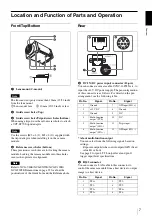
Front/Top/Bottom
a
Lens mount (C-mount)
Note
The lens must not project more than 10 mm (13/32 inch)
from the lens mount.
1
Lens mount face
2
10 mm (13/32 inch) or less
b
Guide screw holes (Top)
c
Guide screw holes/Tripod screw holes (bottom)
When using a tripod, use these four screw holes to attach
a VCT-ST70I tripod adaptor.
Note
Use the screws (M2 × 6 (2); M3 × 8 (2)) supplied with
the tripod adaptor when installing it on the camera
module.
d
Reference screw holes (bottom)
These precision screw holes are for locking the camera
module. Locking the camera module into these holes
secures the optical axis alignment.
Note
Refer to XCG-V60E/XCG-SX97E/XCG-U100E/
XCG-5005E Demensions in page 35 for about the
position/size of the Guide hole and the Reference hole.
Rear
e
DC IN (DC power input) connector (12-pin)
You can connect a camera cable CCXC-12P05N etc. to
input the +12 V DC power supply. The pin configuration
of this connector is as follows. For details on the pin
arrangement, see the following table.
* About multi-function output
You can select from the following signals based on
settings.
Exposure output/strobe control outputs/GPO (fixed
value Hi or Low)
See page 8 for pin 4 TTL output level and pin 11
trigger input level specifications.
f
RJ45 connector
You can connect a LAN cable to this connector to
control the camera module from a host device to output
image to a host device.
Pin No.
Signal
Pin No.
Signal
1
Ground
7
GPI input (ISO +)
2
+12 V DC
8
Ground
3
Ground
9
NC
4
Multi-function
output
*
(TTL)
10
NC
5
Multi-function
output
*
(ISO –)
11
Triger input
6
Multi-function
output
*
(ISO +)
12
GPI input (ISO –)
Pin No.
Signal
Pin No.
Signal
1
TP1 +
5
TP3 –
2
TP1 –
6
TP2 –
3
TP2 +
7
TP4 +
4
TP3 +
8
TP4 –

