background image

4

NW-E50/E70

4

As you did in step 3, adjust the settings
for “month” and “date.”

After rotating the Shuttle switch to adjust the
“date” setting and pressing the 

Nx

 button

to confirm, the display switches to the time
setting screen.

0 : 0 0

5

Rotate the Shuttle switch to adjust the
“hour” setting and press the 

Nx

button to confirm.

The “minute” digit blinks.

0 : 0 0

6

As you did in step 5, adjust the settings
for “minute.”

After rotating the Shuttle switch to adjust the
“minute” setting and pressing the 

Nx

button to confirm, the display switches to the
time setting screen.

D A

T E - T I M E

7

Press the MENU button.

The display returns to the normal screen.

Select [RETURN] in the menu screen or press the MENU
button.

Press the MENU button and hold it.
You can display the current time while pressing the
button.

Notes

• If the unit is not used for a long time, your settings of

the date and time may be reset.

• If the current time is not set, the display for the date and

time will be “-- --.”

• If PC CLK is set to “ON”, the time setting of your

Network Walkman is automatically adjusted to a 
computer’s built-in clock when your Network Walkman
is connected to the computer.

• Depending on the shipping area, the time display

format of the unit is set to a 12-hour display or a 24-
hour display.
You cannot switch between a 12-hour display and a 24-
hour display in the unit.
A 24-hour display is shown in this manual.

To cancel the menu mode

To display the current time

Adjusting the
current time
setting (DATE-
TIME)

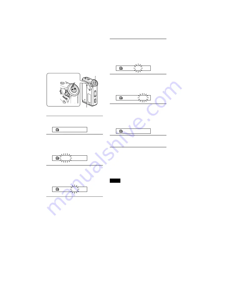
You can set and display the current time.

1

Press the MENU button.

The menu screen is displayed.

R E P E A T

M O D E

>

2

Rotate the Shuttle switch to select
“DATE-TIME” and press the 

Nx

button to confirm.

The “year” digit blinks.

2 0 0 4 y

1 m

1 d

3

Rotate the Shuttle switch to adjust the
“year” setting and press the 

Nx

button to confirm.

The “month” digit blinks.

2 0 0 4 y

1 m

1 d

G

rou

p

M

o

d

e

o

d

e

Shuttle switch

Press
(Confirm)

Nx

 button

MENU button

to (+/

>

)

to (

.

/–)

Содержание Walkman NW-E50

Страница 1: ...132 kbps 5 hr 20 min 105 kbps 8 hr 30 min 66 kbps MP3 2 hr 00 min 256 kbps 4 hr 00 min 128 kbps NW E70 The values for ATRAC3 ATRAC3plus apply if the MP3 file manager software has been erased from the built in flash memory Output Headphone Stereo mini jack 56 Operating temperature 5 C to 35 C 67 F to 95 F Power source LR03 Size AAA alkaline battery Battery life continuous playback ATRAC3 format App...

Страница 2: ...or too long so be careful Strong viscosity Unleaded solder is more viscous sticky less prone to flow than ordinary solder so use caution not to let solder bridges occur such as on IC pins etc Usable with ordinary solder It is best to use only unleaded solder but unleaded solder may also be added to ordinary solder IC400 microcomputer and IC450 nor flash sram on MAIN board cannot be replaced indivi...

Страница 3: ...utton 0 VOLUME button qa HOLD Locking controls switch qs USB jack qd Battery compartment G r o u p M o d e 1 2 3 4 5 6 7 8 9 0 qz OPEN qs qd 1 Strap hole for attaching the strap 2 REPEAT SOUND button 3 MENU button You can switch to the Time display by pressing the MENU button for a while 4 GROUP button 5 Display 6 ACCESS lamp 9 Shuttle switch ...

Страница 4: ...e and time may be reset If the current time is not set the display for the date and time will be If PC CLK is set to ON the time setting of your Network Walkman is automatically adjusted to a computer s built in clock when your Network Walkman is connected to the computer Depending on the shipping area the time display format of the unit is set to a 12 hour display or a 24 hour display You cannot ...

Страница 5: ...ed TEST MODE Nx button The KEY test mode is activated All key inputs are completed then Nx button is pressed restart Be aware that the initialization is included on all key input MENU button EL0 blue lights on off GROUP button EL1 green lights on off All LCD lights and ACCESS LED lights off All LCD lights and ACCESS LED lights on VOL button BEEP turns on VOL button BEEP turns off REPEAT SOUND butt...

Страница 6: ...erical order given Note Disassemble the unit in the order as shown below SET 3 1 CASE CHASSIS FRONT ASSY Page 6 3 2 DISPLAY BOARD ASSY Page 7 3 3 MAIN BOARD ASSY Page 7 3 1 CASE CHASSIS FRONT ASSY MAIN board section 1 case 3 chassis front 4 three button cup 5 window led 2 three claws ...

Страница 7: ...70 3 2 DISPLAY BOARD ASSY 3 3 MAIN BOARD ASSY MAIN board section 4 DISPLAY board 2 tapping screw 1 7 3 cover section 1 lid usb sub assy 4 MAIN board 3 chassis rear ornament assy 2 two claws 1 tapping screw B1 7x7 ...

Страница 8: ... MΩ Voltage variations may be noted due to normal produc tion tolerances Waveforms are taken with a oscilloscope Voltage variations may be noted due to normal produc tion tolerances Circled numbers refer to waveforms Signal path F PLAY a DIGITAL OUT k DIGITAL IN z Waveforms Note on Printed Wiring Board X parts extracted from the component side Y parts extracted from the conductor side Pattern from...

Страница 9: ...CLK 2 8V L801 D801 2 8V 2 3V PI5 PC3 SCK0 SO0 PE7 AN3 SO1 SI1 SCK1 AN2 AN1 PG1 INT5 PFO INT3 RST PI1 PC2 PF3 AOUTR AOUTL PI3 VCC XSTBY FCE0 FRB0 FCLE FAD0 7 A1 19 D0 15 FRE FWP FWE FALE CSI WE RE CS0 LB UB CE R B CLE I O1 8 A1 19 DQ0 15 RE WP WE ALE BES WE OE BEF LBS UBS EL ELEMENT LIQUID CRYSTAL DISPLAY CLOCK OSC IC700 IC801 EL DRIVER SYSTEM CONTROLLER IC400 D703 X700 32kHz S706 HOLD S708 GROUP C...

Страница 10: ...10 10 4 2 PRINTED WIRING BOARD DISPLAY BOARD SIDE A Uses unleaded solder DISPLAY BOARD SIDE A 1 2 23 24 CN402 11 11 LIQUID CRYSTAL DISPLAY A MAIN BOARD CN401 Page 14 1 862 329 1 20 1 2 A B C D E F 3 4 5 6 7 8 9 10 ...

Страница 11: ...00 C 7 0 0 S705 TP701 R704 S704 TP805 TP850 R701 R700 TP851 C702 S701 S708 TP705 TP803 TP802 TP801 TP853 TP852 ACCESS MENU REPEAT SOUND GROUP DISPLAY BOARD SIDE B IC 801 EL ELEMENT 11 11 1 862 329 E BATTERY BACK UP SECONDARY 1 2 A B C D E F 3 4 5 6 7 8 9 10 11 4 3 PRINTED WIRING BOARD DISPLAY BOARD SIDE B Uses unleaded solder ...

Страница 12: ...R704 C702 C802 D801 L801 R801 R805 R802 R803 R804 C801 TP804 TP852 TP410 S708 S705 C522 TP805 Q701 CN402 R850 R851 R852 C700 SM8145AB G EL SML 512DWT86 100 47k 100k BATTERY BACK UP SECONDARY 1k VDD_RTC RB520S 30TE61 0 47 0 47 0 1 0 1 20P VDD LCDDA EL1 LCDRST LCDCS ADK2 GROUP 47k 22k 22k 100p 4700p 1SS376TE 17 100k 150k 33k 47k 33k 0 01 VDD_EL LCDCK EL2 1 GND 2SC5658T2L 24P 100k 100k 150k ...

Страница 13: ...A B C D E F G 3 4 5 6 7 8 9 10 11 IC450 IC400 IC461 IC301 C402 4 5 PRINTED WIRING BOARD MAIN SIDE A Uses unleaded solder IC400 microcomputer and IC450 nor flash sram on MAIN board cannot be replaced individually Replace it with MAIN board assembly for service Semiconductor Location Ref No Location D300 C 8 IC301 D 9 IC400 C 4 IC450 E 2 IC461 D 7 ...

Страница 14: ...1 1 3 3 3 2 4 4 4 5 5 1 1 1 3 3 3 4 4 4 5 5 5 S E E E E S E S OFF ON 1 3 2 4 IC510 1 3 2 4 1 1 3 3 2 2 4 4 R534 1 2 A B C D E F G 3 4 5 6 7 8 9 10 11 4 6 PRINTED WIRING BOARD MAIN SIDE B Uses unleaded solder Semiconductor Location Ref No Location D501 B 8 D502 C 10 D503 D 10 D504 C 8 IC500 E 10 IC501 B 5 IC502 B 5 IC503 C 8 IC504 B 6 IC505 D 5 IC506 C 11 IC507 E 9 IC508 D 6 Ref No Location IC509 B...

Страница 15: ...4 VDR700 R725 R723 R709 TP702 C701 TP412 R416 C704 C705 C706 R400 VDR400 C401 TP406 R401 R722 TP701 C707 X700 IC700 R461 C462 VDR405 R716 R715 R463 R726 R727 R729 S706 C703 R410 R453 C464 R462 S707 S703 R714 C416 R404 R728 CN401 X400 R421 C409 C410 0 1 0 1 0 1 0 10k PD4 0 1 TXD0 TXD0 TXD0 TXD0 MSINS MSDIS 10k MSSCLK MSBS MSPWR XMS 0 1 0 1 XBOOT 0 1 10p 0 1 220 16MHz 1M 22 1 1 1 5k 22 22 0 2 2M 100...

Страница 16: ...302 R503 R525 C510 CN400 NJM2776RB2 TE2 0 22 47k 33k 47k 0 22 100p 0 1 0 33 10 0 22 0 022 4 7k 0 022 0 22 10 47k 0 1 0 100p HP R HP L 0 2 3V 0 1 D D 1 2V 0 0 R534 100 RSX101M 30TR 33p 470k 100k 100k 470k 2SC5658T2L 0 047 470k 1M REGCE 0 1 0 01 1M 470k 2SC5658T2L 1M 0 022 470k 47K 100k 2 2M 470k VCORE 3LN01S K TL E S 80809CNBB B9N TF 1SS400TE 61 1SS400TE 61 0 1 10 47k 220k 470k RSX101M 30TR 1M 470k...

Страница 17: ...TER I O CONTROL ADDRESS DECODER SHIFT REGISTER INTERRUPT CONTROL OSC DETECT VOLTAGE DETECT ALARM W REGISTER WEEK MIN HOUR ALARM D REGISTER MIN HOUR DIV OSC DIVIDER CORRECTION 9 10 8 7 6 2 3 4 5 1 TIMER COUNTER SEC MIN HOUR WEEK DAY MONTH YEAR LDR NC NC OCL1 OCL2 NC OCL3 OCE ENA2 ENA1 NC VDD NC OUT2 OUT1 NC NC CHV OUTCOM VSS 20 19 18 17 16 15 14 13 12 11 1 2 3 4 5 6 7 8 9 10 OSCILLATOR OSCILLATOR D...

Страница 18: ...emarks Ref No Part No Description Remarks 5 1 OVERALL ASSY SECTION 1 2 4 6 7 10 11 9 8 3 not supplied MAIN board section 5 1 3 266 585 01 CASE 2 3 266 593 01 CHASSIS FRONT SILVER WHITE E50 2 3 266 593 11 CHASSIS FRONT BLUE E50 2 3 266 593 21 CHASSIS FRONT RED E50 2 3 266 593 31 CHASSIS FRONT HAIR LINE SILVER E70 2 3 266 593 41 CHASSIS FRONT BLUE E70 2 3 266 593 51 CHASSIS FRONT WHITE E70 3 3 266 5...

Страница 19: ... ADHESIVE 58 3 266 582 01 BUTTON VOL 59 3 266 595 01 SHEET VOL 60 2 048 634 01 SHEET FRONT ADHESIVE 61 3 266 594 01 CHASSIS REAR SILVER E50 WHITE 61 3 266 594 11 CHASSIS REAR BLUE 61 3 266 594 21 CHASSIS REAR RED 61 3 266 594 31 CHASSIS REAR SILVER E70 HAIR LINE 62 X 2021 522 1 MAIN BOARD COMPLETE E50 62 X 2021 523 1 MAIN BOARD COMPLETE E70 63 3 266 606 01 SHAFT PLAY 64 3 266 610 01 KNOB SHUTTLE 6...

Страница 20: ...4 406 41 INDUCTOR 220uH TRANSISTOR Q701 8 729 056 42 TRANSISTOR 2SC5658T2L RESISTOR R460 1 218 977 11 RES CHIP 100K 5 1 16W R700 1 218 973 11 RES CHIP 47K 5 1 16W R701 1 218 969 11 RES CHIP 22K 5 1 16W R704 1 218 969 11 RES CHIP 22K 5 1 16W R706 1 218 977 11 RES CHIP 100K 5 1 16W R708 1 218 973 11 RES CHIP 47K 5 1 16W R710 1 218 953 11 RES CHIP 1K 5 1 16W R713 1 218 941 81 RES CHIP 100 5 1 16W R80...

Страница 21: ...709 1 125 777 11 CERAMIC CHIP 0 1uF 10 10V CONNECTOR CN400 1 818 513 11 CONNECTOR SQUARE TYPE USB 5P CN401 1 818 410 21 CONNECTOR BOARD TO BOARD 24P DIODE D300 8 719 056 59 DIODE MAZS120008SO D501 6 500 460 01 DIODE RSX101M 30TR D502 8 719 069 28 DIODE 1SS400TE 61 D503 8 719 069 28 DIODE 1SS400TE 61 D504 6 500 460 01 DIODE RSX101M 30TR FERRITE BEAD FB100 1 469 082 21 INDUCTOR FERRITE BEAD 1005 FB2...

Страница 22: ... 985 11 RES CHIP 470K 5 1 16W R524 1 218 989 11 RES CHIP 1M 5 1 16W R525 1 218 989 11 RES CHIP 1M 5 1 16W R526 1 208 935 11 METAL CHIP 100K 0 5 1 16W R527 1 218 985 11 RES CHIP 470K 5 1 16W R528 1 208 935 11 METAL CHIP 100K 0 5 1 16W R529 1 218 989 11 RES CHIP 1M 5 1 16W R530 1 218 985 11 RES CHIP 470K 5 1 16W R531 1 218 990 11 SHORT CHIP 0 R532 1 218 990 11 SHORT CHIP 0 R533 1 218 990 11 SHORT CH...

Страница 23: ... 3 267 071 71 MANUAL INSTRUCTION KR 3 267 136 01 APPLICATION SOFT CD ROM SS2 0 MP3MGR SonicStage 3 267 746 61 MANUAL APPLI INSTRUCTION SonicStage ENGLISH CH HK TW 3 267 746 71 MANUAL APPLI INSTRUCTION SonicStage SIMPLIFIED CHINESE TRADITIONAL CHINESE CH HK TW 4 220 438 21 PIECE M EAR E70 4 220 439 21 PIECE S EAR E70 8 912 717 90 RECEIVER MDR EX051SP E70 8 953 218 91 RECEIVER MDR E838SP E50 Ver 1 1...

Страница 24: ...to jump to the next revised page Ver Date Description of Revision 1 0 2004 04 New 1 1 2004 06 Addition of Hong Kong Korea and Taiwan models 1 2 2004 08 Addition of Part No for the MAIN board of NW E50 in Electricl Parts List SPM 04062 1 3 2004 09 Addition of Part No for NW E70 white model to Ref No 2 and addition of color for Ref No 61 on Exploded Views SPM 04109 ...

Отзывы: