


7
D-E340/E341
Pin No.
Pin name
I/O
Description
SECTION 5
DIAGRAMS
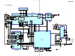
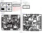
5-1. EXPLANATION OF IC TERMINALS
IC801 (SYSTEM CONTROL) T5AW6-3VK1
1
GND
–
Ground terminal
2
XIN
I
System clock input (4.19MHz)
3
XOUT
O
System clock output (4.19MHz)
4
TEST
I
Test mode terminal (Fixed to “L”)
5
VCPU
–
Power supply for CPU & I/O
6
P21
I
The monitor input of reference voltage of power control
7
BATVCC ON
O
Not used (OPEN)
8
RESET
I/O
Reset terminal
9
FOK.I
I
Focus OK signal input
10
NC
–
Not used (OPEN)
11
SCOR_I
I
SCOR pulse input
12
GRSCOR_I
I
GRSCOR input
13
AMTE_O
O
Mute output
14
XSOE_O
O
Serial enable output
15
XLAT_O
O
Serial latch output
16
MSDTI
I
Serial data input from DSP SENS
17
MSDTO
O
Serial data output
18
MSCK_O
O
Serial interface clock output
19,20
VCPU
–
Power supply for CPU and I/O
21
AD_CHGMNT
I
Charge monitor input
22
AD_BATMNT
I
Battery moniter input
23
AD_KEY2
I
Key input
24
AD_SEL
I
DRAM, LINE OUT DIGITAL OUT select input
25
AD_KEY
I
Set’s key detection input
26
AD_RMCKEY
I
Remote contorol key detection input
27
AD_DCINMNT
I
DC voltage monitoring input
28
OPEN
I
OPEN switch status detection input
29
EXTVCC1
–
External battery monitor
30
BEEP_O
O
Beep sound output
31
NC
–
Not used (OPEN)
–
Not used (OPEN)
I
External battery monitor
I
Not used (OPEN)
O
Not used (OPEN)
I
Not used (Fixd to “H”)
I
Not used (Fixd to “H”)
I
G-PRPTECTION switch status detection input
O
Not used (OPEN)
I
HOLD switch status detection input
O
Not used (OPEN)
42 to 55
SEG1 to 14
O
LCD segment output
56
SEG0
O
Not used (OPEN)
57 to 60
COM0 to 3
O
LCD common output
61 to 63
V1 to 3
–
LCD driver booster
64
C1
–
LCD driver booster
65
C0
–
LCD driver booster
66
XWAKEUP_O
O
Wake-up signal output
www. xiaoyu163. com
QQ 376315150
9
9
2
8
9
4
2
9
8
TEL 13942296513
9
9
2
8
9
4
2
9
8
0
5
1
5
1
3
6
7
3
Q
Q
TEL 13942296513 QQ 376315150 892498299
TEL 13942296513 QQ 376315150 892498299


