Sony TRINITRON KV-G21L3 Скачать руководство пользователя страница 9

 9 

KV
-G21L3

RM-883

Operations

12

-EN

Using the Child Lock
feature

Watching the picture
in wide mode

You can prevent a child from watching certain program
positions by using the buttons on the remote
commander.

1

Select the TV program you want to lock.

2

Press SELECT until “CHILD LOCK” appears
on the screen.

3

Press + or – until “LOCKED” appears on the
screen.

Notes

To unlock the program position, repeat steps 1 to 3 as above
until “LOCKED” disappears from the screen.

To prevent your child from unlocking the program position,
keep the remote commander away from your child.

÷

0

+ or –

SELECT

SELECT

CHILD LOCK

LOCKED

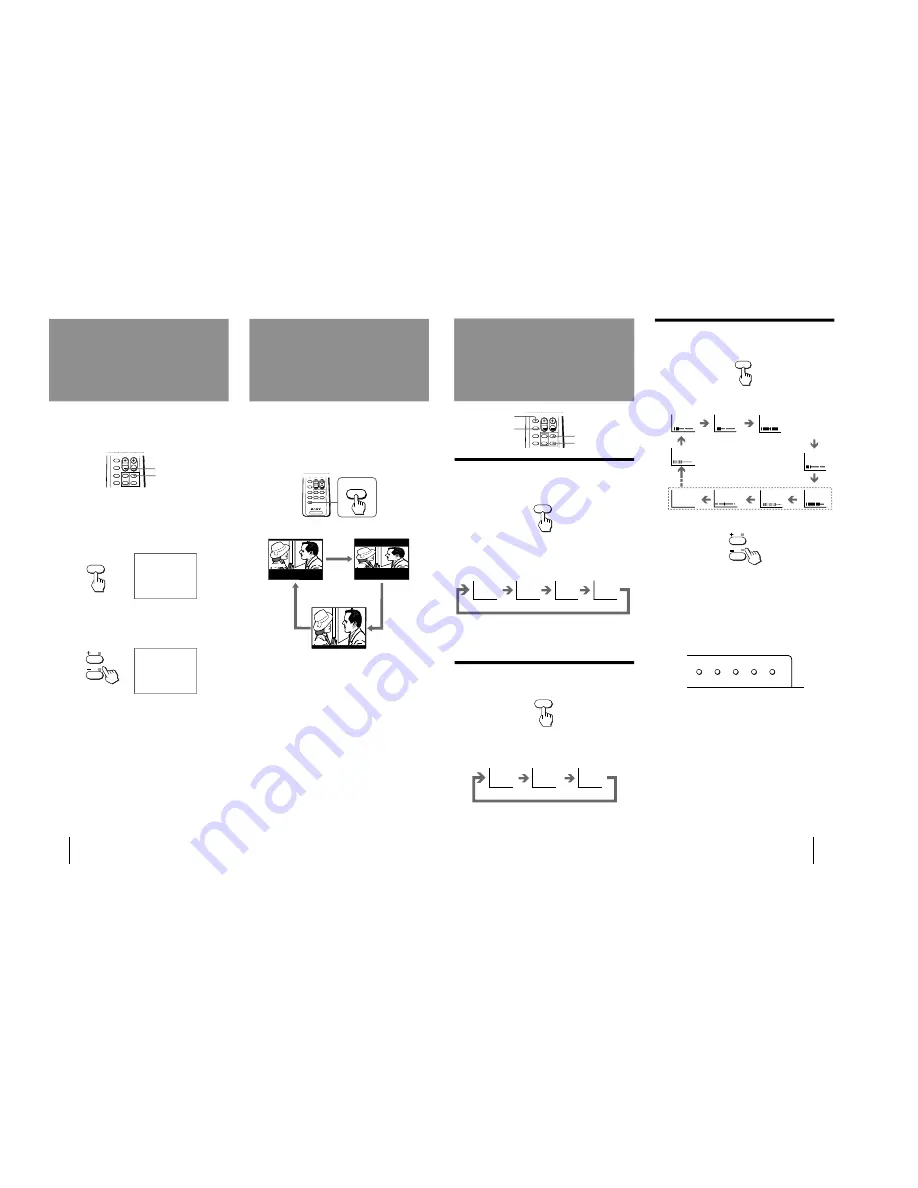
You can adjust the display mode accordingly to fit the
programs to your TV screen size.

Press WIDE/V-ZOOM repeatedly until the wide
display mode you want appears on the screen.

TV

WIDE/

V-ZOOM

G o o d - b y e , J a n e
G o o d - b y e .

G o o d - b y e , J a n e
G o o d - b y e .

WIDE

V-ZOOM

NORMAL

Normal display
mode

“WIDE” mode

“V-ZOOM” mode

Operations

13

-EN

Adjusting the
picture

Adjusting the sound and picture settings

1

Press SELECT until the item you want to
adjust appears.

Each time you press SELECT, the screen changes
as follows:

2

Press + or – to adjust the item.

3

To adjust other items, repeat steps 1 and 2.

Notes

You can also use SELECT and /– on the TV to
adjust the sound and picture settings.

• The on-screen display for BASS, TREBLE, BALANCE and

SURROUND are available for KV-J21MF3 only.

SURROUND is only applicable to a stereo signal. When
receiving a monaural signal, please turn off SURROUND for
the best sound (KV-J21MF3 only).

If the picture color is abnormal when receiving
programs through the 

˘

 (antenna) terminal

Change the “TV SYSTEM” (KV-J21MF3 only) or “COLOR
SYSTEM” setting or adjust the “COLOR” level in the on-screen
display until the color becomes normal.

If the picture color is abnormal when receiving
programs through the video input jack

Change the “COLOR SYSTEM” setting or adjust the “COLOR”
level in the on-screen display until the color becomes normal.

Note

Normally set “COLOR SYSTEM” to “AUTO”.

If the sound is distorted or noisy when receiving
programs through the 

˘

 (antenna) terminal

(KV-J21MF3 only)

Change the “TV SYSTEM” setting in the on-screen display until
the sound becomes clear.

Adjusting the sound
and picture

÷

0

SOUND

MODE

SELECT
PIC MODE

Selecting the sound mode

p

 KV-J21MF3 only

Press SOUND MODE until the mode you want
appears.

Each time you press SOUND MODE, the screen
changes as follows:

Note on the SOUND MODE button (KV-G21L3)

The sound mode feature is unavailable for your TV. Thus, the
SOUND MODE button on the remote commander is not used
for your TV.

Selecting the picture mode

Press PIC MODE until the mode you want
appears.

Each time you press PIC MODE, the screen changes as
follows:

Note

If you change the picture and sound mode after the following
adjustments, the adjustment changes in accordance with the
picture and sound mode.

SELECT

+ or –

SOUND

MODE

 MUSIC

 DRAMA

 SPORTS

 SOFT

PIC MODE

DYNAMIC

STANDARD

SOFT

High contrast
picture

Soft picture

Normal
picture

Emphasize
low and high
sound effect

Emphasize
huge
audience
atmosphere

Emphasize
vocals and
background
music

Emphasize
soft sound

PICTURE

COLOR

BRIGHT

HUE

SHARPNESS

BASS

BALANCE

SURROUND

TREBLE

(Operative for
NTSC signal only)

(KV-J21MF3 only)

Front of TV

MANUAL PROGR

COLOR SYSTEM

R

SELECT

TV SYSTEM

AUTO PROGR

Содержание TRINITRON KV-G21L3

Страница 1: ...TRINITRON COLOR TV MODEL COMMANDER DEST CHASSIS NO KV G21L3 RM 883 ME SCC J35Y A SERVICE MANUAL MODEL COMMANDER DEST CHASSIS NO BG 1S D CHASSIS ...

Страница 2: ...FICATIONS Note Power requirements 110 240 V AC 50 60 Hz Power consumption W Indicated on the rear of the TV Television system B G Color system PAL PAL 60 SECAM NTSC4 43 NTSC3 58 AV IN Channel coverage VHF E2 to E12 UHF E21 to E69 CATV S01 to S03 S1 to S41 Audio output speaker 3W Inputs Antenna 75 ohms VIDEO IN jacks phono jacks Video 1 Vp p 75 ohms Audio 500mVrms high impedance Outputs Earphone ja...

Страница 3: ...ematic Diagram of A Board 31 2 Schematic Diagram of C Board 35 6 4 Semiconductors 37 7 EXPLODED VIEW 39 8 ELECTRICAL PARTS LIST 41 1 GENERAL 4 2 DISASSEMBLY 2 1 Rear Cover Removal 11 2 2 A Board Removal 11 2 3 Service Position 11 2 4 Replacement of parts 12 2 4 1 Replacement of Multi Button 12 2 4 2 Replacement of Light Guide and Power Button 12 2 5 Demagnetization Coil Removal 12 2 6 Picture Tube...

Страница 4: ...s mentioned here are partial abstracts from the Operating Instructions Manual The page numbers of the Operating Instruction Manual remain as in the manual 2 MONITOR OUT AUDIO VIDE O VIDEO IN 1 2 3 3 B G I D K M TV SYSTEM AUTO PROGR TV SYSTEM AUTO PROGR p KV J21MF3 ...

Страница 5: ...an connect optional audio video equipment to your TV such as a VCR multi disc player camcorder video game or stereo system Connecting video equipment using video input jacks p KV G21L3 When connecting a monaural VCR Connect the yellow plug to VIDEO and the black plug to AUDIO L MONO p KV G21L3 When using the video input jacks Do not connect video equipment to the video input jacks at the front and...

Страница 6: ...SYSTEM is memorized for each program position Disabling program positions using the buttons on the TV By disabling unused or unwanted program positions you can skip those positions when you press PROGR on the remote commander 1 Press PROGR on the remote commander until the unused or unwanted program position appears on the screen 2 Press MANUAL PROGR 3 Press PIC MODE on the remote commander 4 Pres...

Страница 7: ... is turned on in standby mode press POWER on the remote commander 2 Press SELECT until TV SYSTEM appears KV J21MF3 only 3 Press or to select your local TV system KV J21MF3 only 4 Press SELECT until AUTO PROGRAM appears 5 Press or 6 Press or Presetting channels manually using the remote commander 1 Press SELECT until TV SYSTEM appears KV J21MF3 only 2 Press or to select your local TV system KV J21M...

Страница 8: ...lay language 1 Press SELECT until the screen appears as follows 2 Press or to select Note You can also use SELECT and VOLUME on the TV to Setting the Wake Up Timer You can set the TV to automatically turn on as you have programmed 1 Press WAKE UP INDEX repeatedly to set the timer The on screen display appears and the WAKE UP indicator on the TV lights up 2 If you want a particular TV program or vi...

Страница 9: ...color is abnormal when receiving programs through the antenna terminal Change the TV SYSTEM KV J21MF3 only or COLOR SYSTEM setting or adjust the COLOR level in the on screen display until the color becomes normal If the picture color is abnormal when receiving programs through the video input jack Change the COLOR SYSTEM setting or adjust the COLOR level in the on screen display until the color be...

Страница 10: ...Good picture Noisy sound Check the TV SYSTEM setting KV J21MF3 only Reduce the TREBLE level or select the SOFT sound mode KV J21MF3 only Good picture No sound Press VOLUME Press MUTING TV cabinet creaks Even if the picture or the sound is normal changes in the room temperature sometimes make the TV cabinet expand or contract making a noise This does not indicate a malfunction Note on the remote co...

Страница 11: ... 11 KV G21L3 RM 883 2 1 REAR COVER REMOVAL 2 2 A BOARD REMOVAL 2 3 SERVICE POSITION SECTION 2 DISASSEMBLY 2 Two screws BVTP 4 16 3 One screw BVTP 3 16 1 Two screws BVTP 4 16 A board Lever Lever A board ...

Страница 12: ...1 DEMAGNETIZATION COIL 2 TENSION SPRING PICTURE TUBE ill2 02 0 1_ES29 ...

Страница 13: ...then pull up the rubber cap firmly in the direction indicated by the arrow b 3 When one side of the rubber cap is separated from the anode button the anode cap can be removed by turning up the rubber cap and pulling it up in the direction of the arrow c c Anode button HOW TO HANDLE AN ANODE CAP 1 Do not damage the surface of anode caps with sharp shaped objects 2 Do not press the rubber too hard s...

Страница 14: ...put a white signal with the pattern generator Contrast Brightness 2 Set the pattern generator raster signal to a green raster 3 Move the deflection yoke to the rear and adjust with the purity control so that the green is at the center and the blue and the red take up equally sized areas on each side See Figures 3 1 through 3 3 4 Move the deflection yoke forward and adjust so that the entire screen...

Страница 15: ... points are on top of each other at the center of the screen 3 Tilt the V STAT magnet and adjust the static convergence by opening or closing the V STAT magnet B R B R a b b b a b a b a R G B b B G R b b a a 1 2 3 G G B G R R G B Operation of V STAT magnet If the V STAT magnet is moved in the direction of the a and b arrows the red green and blue points move as shown below Operation of BMC Hexapol...

Страница 16: ...ion Before starting this adjustment adjust the horizontal static convergence and the vertical static convergence 1 Slightly loosen the deflection yoke screws 2 Remove the deflection yoke spacer 3 Screen corner Convergence a d screen corner misconvergence b a c d B G R B G R R G B R G B R G B R G B B G R B G R R G B B G R B G R R G B a d c b Fix a Permalloy assy corresponding to the misconverged ar...

Страница 17: ... plug into AC outlet again 2 Turn the power switch ON and set to Service Mode 3 Call the adjusted items again to confirm adjustments were made Item number Note Adjustment item Initial DATA 09 RDR 25 WHITE POINT R 0A GDR 20 WHITE POINT G 0B BDR 20 WHITE POINT B 3 4 G2 SCREEN AND WHITE BALANCE ADJUSTMENTS 1 G2 SCREEN ADJUSTMENT RV701 1 Set the PICTURE and BRIGHTNESS to normal 2 Put to VIDEO input mo...

Страница 18: ...d number of times Flickering is operated by lighting the LED s for 60ss each time The flickering frequency responding to each failed device is shown below All the devices are checked one after another from the left of the table If an error is found the responding LED will start flickering So if more than 1 device have failed only the one on the left side will flicker Device Flickering Frequency NO...

Страница 19: ...E p SOUND MODE VOL PROGR RM 883 g POWER DISP REVEAL MUTING TV VIDEO HOLD TEXT A B ENLARGE WIDE V ZOOM WAKE UP INDEX SLEEP TEXT CLR 1 2 3 4 6 7 8 9 0 p p 5 TV 7 0 All data becomes the values in memory 8 0 All user control goes to the standard state 5 0 Service data initialization Be sure not to use usually 2 0 Write 50Hz adjustment data to 60Hz or viceversa The screen display is SERVICE Mode 08 Dat...

Страница 20: ...The SERVICE display will change to WRITE 5 Execute the writing with the 0 button The WRITE display will be changed back to SERVICE Use the same method for Items Number 00 33 Use 1 and 4 to select the adjustment item use 3 and 6 to adjust write with MUTING then execute the write with 0 Write executed with 0 Written with the MUTING WRITE WRITE GREEN 0C VSF 08 SERVICE 50 50 50 GREEN 0C VSF 08 GREEN T...

Страница 21: ...0 OVER VOLTAGE INPUT TDA8375 17 COR 00 01 00 TV Video Text NOISE CORING PEAK TDA8375 18 PMX 00 3F 2D TV Video PICTURE MAX DATA TDA8375 19 PMI 00 3F 00 PICTURE MIN DATA TDA8375 1A SBR 00 7F 4B SUB BRIGHTNESS TDA8375 1B SHU 00 0F 07 SUB HUE TDA8375 1C SSH 00 03 01 SUB SHARPNESS TDA8375 1D SC1 00 3F 1F SUB COLOR LOWER TDA8375 1E SC2 00 3F 0D SUB COLOR HIGHER TDA8375 1F AIP 00 7F 3F ADJUSTMENT IF PLL ...

Страница 22: ...n interlace TEXT Mode 0 Non interlace 1 Interlace 29 ABL Bright ABL ON OFF ON 1 OFF 0 31 OP0 32 OP1 33 OP2 Input data are different according to models AV INPUT 00 NO MODEL 01 MONO CXA1315 10 11 STEREO TDA8424 TV System 00 Multi model 01 B G 10 D K I 11 B G D K NTSC SECAM Chin No 31 OP0 Input data are different according to models Item Video Text Volume 1 Thai B TV System NT3 58 SECAM Reserved KV ...

Страница 23: ...elect item numbers and 31 OP0 32 OP1 and 33 OP2 and set the bit per model with command buttons 3 and 6 5 Press commander buttons 8 and Test Normal to return all user adjustments to the data that was set on shipment from the factory Cancel Service Mode 5 4 PICTURE DISTORTION ADJUSTMENT Item Number 00 08 00 HSF H SHIFT 01 HSZ H SIZE 02 PAP PIN AMP 03 CNP CORNER PIN 04 TLT TILT 05 VSL V SLOP 06 VAP V...

Страница 24: ... 24 KV G21L3 RM 883 MEMO ...

Страница 25: ...ANUAL TV SYS SELECT COL SYS PROGR PROGR R G B IK 1 4 2 7 9 10 5 6 11 13 17 16 15 14 13 11 2 3 4 5 8 7 T605 LFT 1 2 T801 H2 V901 PICTURE TUBE 6 5 7 1203 VIDEO L MONO IN 1 VIDEO FRONT REAR VIDEO IN 1 L MONO VIDEO 17 CVBS IN 3 5 7 IC1211 L SW IC1210 BUFFER CLK DAT R Y B Y SYNC R Y B Y IN OUT RESET 55 DEEMP AUDIO Q1209 B G SW Q414 Q406 408 Q409 CT55 CF55 SYNC FILTER 13 CVES IN SYNC FILTER Q1201 1202 V...

Страница 26: ... A 5 TRANSISTOR Q001 F 7 Q030 C 12 Q108 C 2 Q109 E 12 Q110 E 3 Q202 A 8 Q207 B 10 Q208 B 11 Q209 B 9 Q210 B 9 Q301 C 7 Q302 C 7 Q303 C 8 Q351 E 9 Q401 C 3 Q402 D 3 Q403 E 4 Q404 E 4 Q406 B 6 Q408 A 6 Q409 A 6 Q414 C 5 Q417 B 6 Q551 F 6 Q552 F 5 Q561 I 6 Q601 G 11 Q801 E 2 Q802 G 1 Q821 E 6 Q902 H 13 Q903 H 13 Q1201 A 2 Q1202 A 2 Q1203 A 3 Q1204 B 3 Q1207 A 3 Q1208 A 3 Q1209 C 4 Q1264 B 3 Q1265 B 2...

Страница 27: ...UTTON POWER 8 1 504 305 11 SPEAKER 5X12CM 9 4 043 388 11 SCREW STEP TAPPING 10 4 054 468 01 SHEET BLOTTING 11 4 365 808 01 SCREW 5 TAPPING 12 8 738 774 05 PICTURE TUBE A51JUH71X 13 8 451 280 33 DEFLECTIONYOKE Y21PXA2 14 1 452 277 00 MAGNET BMC 15 A 1332 019 A C BOARD MOUNTED 16 4 046 600 11 SPACER DY 17 3 704 372 41 HOLDER HV CABLE 18 4 369 318 61 SPRING TENSION 19 1 409 942 11 COIL DEMAGNETIZATIO...

Страница 28: ...R 0 01MF 5 50V C329 1 130 478 00 MYLAR 0 0039MF 5 50V C330 1 136 165 00 MYLAR 0 1MF 5 50V C331 1 126 964 51 ELECT 10MF 20 50V C332 1 136 165 00 MYLAR 0 1MF 5 50V C333 1 136 165 00 MYLAR 0 1MF 5 50V C334 1 102 123 00 CERAMIC 0 0033MF 10 50V C335 1 102 973 00 CERAMIC 100PF 5 50V C336 1 126 964 51 ELECT 10MF 20 50V C337 1 126 933 11 ELECT 100MF 20 16V C339 1 101 361 00 CERAMIC 150PF 5 50V C340 1 102 ...

Страница 29: ... 109 54 DIODE RD2 2ESB2 D310 8 719 911 19 DIODE 1SS119 25 D311 8 719 109 54 DIODE RD2 2ESB2 D312 8 719 110 08 DIODE RD8 2ESB2 D315 8 719 121 26 DIODE RD9 1ESL2 D351 8 719 908 03 DIODE GP08D D399 8 719 121 26 DIODE RD9 1ESL2 D403 8 719 911 19 DIODE 1SS119 25 D513 8 719 109 84 DIODE RD5 1ESB1 D551 8 719 908 03 DIODE GP08D D561 8 719 911 19 DIODE 1SS119 25 D591 8 719 911 19 DIODE 1SS119 25 D601 8 719...

Страница 30: ... 2SD1878 CA Q821 8 729 209 15 TRANSISTOR 2SD2012 Q902 8 729 030 02 TRANSISTOR DTC144ESA Q903 8 729 030 02 TRANSISTOR DTC144ESA Q1201 8 729 119 79 TRANSISTOR 2SC2785 FEK Q1202 8 729 119 79 TRANSISTOR 2SC2785 FEK Q1203 8 729 119 79 TRANSISTOR 2SC2785 FEK Q1204 8 729 119 76 TRANSISTOR 2SA1175 HFE Q1207 8 729 119 79 TRANSISTOR 2SC2785 FEK Q1208 8 729 119 79 TRANSISTOR 2SC2785 FEK Q1209 8 729 119 79 TR...

Страница 31: ... 1 4W R340 1 249 411 11 CARBON 330 5 1 4W R341 1 249 417 11 CARBON 1K 5 1 4W R344 1 259 880 11 CARBON 2 2M 5 1 4W R351 1 249 393 11 CARBON 10 5 1 4W R355 1 249 393 11 CARBON 10 5 1 4W R356 1 249 417 11 CARBON 1K 5 1 4W R360 1 259 884 11 CARBON 4 7M 5 1 4W R403 1 249 403 11 CARBON 68 5 1 4W R406 1 247 847 31 CARBON 4 7K 5 1 4W R407 1 249 424 11 CARBON 3 9K 5 1 4W R408 1 249 420 11 CARBON 1 8K 5 1 4...

Страница 32: ... 1 249 428 11 CARBON 8 2K 5 1 4W R913 1 247 823 31 CARBON 470 5 1 4W R914 1 247 823 31 CARBON 470 5 1 4W R915 1 249 428 11 CARBON 8 2K 5 1 4W R1201 1 249 404 00 CARBON 82 5 1 4W R1202 1 249 417 11 CARBON 1K 5 1 4W R1203 1 249 437 11 CARBON 47K 5 1 4W R1205 1 249 404 00 CARBON 82 5 1 4W R1206 1 249 437 11 CARBON 47K 5 1 4W R1211 1 249 403 11 CARBON 68 5 1 4W R1212 1 249 417 11 CARBON 1K 5 1 4W R121...

Страница 33: ...DE 1SS119 25 D717 8 719 121 26 DIODE RD9 1ESL2 JACK J701 1 251 239 11 SOCKET CRT COIL L701 1 410 667 31 INDUCTOR 22UH TRANSISTOR Q704 8 729 326 11 TRANSISTOR 2SC2611 Q705 8 729 326 11 TRANSISTOR 2SC2611 Q706 8 729 326 11 TRANSISTOR 2SC2611 Q707 8 729 200 17 TRANSISTOR 2SA1091 O Q708 8 729 200 17 TRANSISTOR 2SA1091 O Q709 8 729 200 17 TRANSISTOR 2SA1091 O Q710 8 729 230 91 TRANSISTOR 2SC3113 B TP Q...

Страница 34: ... ANTENNA TELESCOPIC 1 574 062 61 CORD POWER WITH CONNECTOR 2 5A 250V 1 900 700 05 LEAD ASSY FOCUS 8 451 280 33 DEFLECTIONYOKE Y21PXA2 8 738 774 05 PICTURE TUBE A51JUH71X ACCESSORIES AND PACKING MATERIALS 3 701 910 00 SCREW SPECIAL DIA 3 8X20 3 862 021 21 MANUAL INSTRUCTION 4 392 004 21 CLIP 4 392 003 31 BAND HOLD 4 050 141 01 INDIVIDUAL CARTON 4 053 003 01 BAG PROTECTION 4 067 570 01 CUSHION UPPER...

Отзывы: